Getting Started with the 3D Cloud Asset Management System (AMS)
Introduction
Welcome to the 3D Cloud™ Asset Management System (AMS) User Guide.
The AMS is the backbone of the 3D Cloud platform, connecting 3D assets, product data, your business rules and workflows to produce amazing 3D visualizations for your customers. Whether you are a 3D Cloud client or a 3D Cloud associate, this user guide is meant to be a resource for you to understand the basics of all of the tools available in the system. With the AMS, you’ll be able to create 3D content orders, manage 3D content and data, build product configurators, and create product renderings.
Key Features of the 3D Cloud AMS
Authentication System - Controls secure logins for users with role based permissions
Client and Application Management Tools - Used to keep track of deployed software
Art and Content Management Tools - Robust tools to order, import, onboard and manage 3D Models, Textures, Materials, Images and other related assets
Data Manipulation Tools - Tools to assist users in managing content
Reports - Tools to report the status of products and other pieces of content
System Requirements
Requirement | Details |
|---|---|
Operating System | Windows 10 or higher, macOS 10.14 or higher |
Browser | Latest versions of Chrome, Firefox, Safari, or Edge |
Internet Connection | Stable broadband connection |
Additional Software | The latest version of Adobe Acrobat Reader for PDF documents |
Sign Up / Create an Account
In order to get started logging into 3D Cloud (cms.3dcloud.io), you must have an account already setup by the internal 3D Cloud team with permissions to access the appropriate client.
Logging In
To login follow these steps:
Visit cms.3dcloud.io
Use your 3D Cloud email and provided password, then click the blue Log In button.

Forgot Password
If you forgot your password, use the Forgot password? link. A password reset email will be sent to you with a link to the reset process.
Log in with SSO
Users are welcome to use the Single-Sign On (Log in with SSO) button to log into the 3D Cloud AMS. This is a convenience feature so users do not have to remember a new username and password. If you are logged into a Google account, you can access the AMS.
When someone logs in with SSO, it will convert any existing user account to an SSO user. An SSO account cannot be set up in the User Manager.
Using an SSO login changes nothing about interacting with the 3D Cloud AMS vs. a non-SSO login.
Note: Once logged in using SSO, an SSO user can no longer use a previous username/password to log in to AMS. The user account is now locked to SSO.
If a user (e.g. internal 3D Cloud administrator) still needs to login with username/password, like for older WLA implementations that don't support it, we can create a "legacy" account. This would use their email with a “+lgy” suffix. Example: firstname+lgy@3dcloud.com. This account cannot be used for SSO login, and should not be used as a way to connect to the AMS. The legacy account is purely to get through splash screen logins like we see on older WLA (<V9.2). Legacy accounts will only be granted the minimum access needed for splash screen logins.
General Layout
The 3D Cloud AMS may appear slightly different depending on whether you are a 3D Cloud associate/administrator or a 3D Cloud client. The site functions are the same, though the main navigation may have slightly different labels in the navigation.
Upon log in as a 3D Cloud Associate/Adminstrator user, you will see this home screen:
A
header barwith 3D Cloud logo, navigation bar, client and application selection dropdown menus, a notification bell and profile icon. From left-to-right:The
navigation barextends across the top of the page and includes all the main sections and pages in the system.The
client menuappears at the upper right as a dropdown menu.The
client application menuappears to the right of the client menu as a dropdown, and shows the applications related to the current client selected.The
notification bellkeeps you up to date with events within the system.The
profile iconallows the user to edit theme/visual settings and profile information. For admin users, the ability to edit users and permissions is provided here.
Lastly, the primary main section appears below the header bar. In the screenshot above, the
Homepage is shown, with the ability to “Create a new client” or search for a specific client.
Upon log in as a 3D Cloud Client user, you will see this as your home screen:
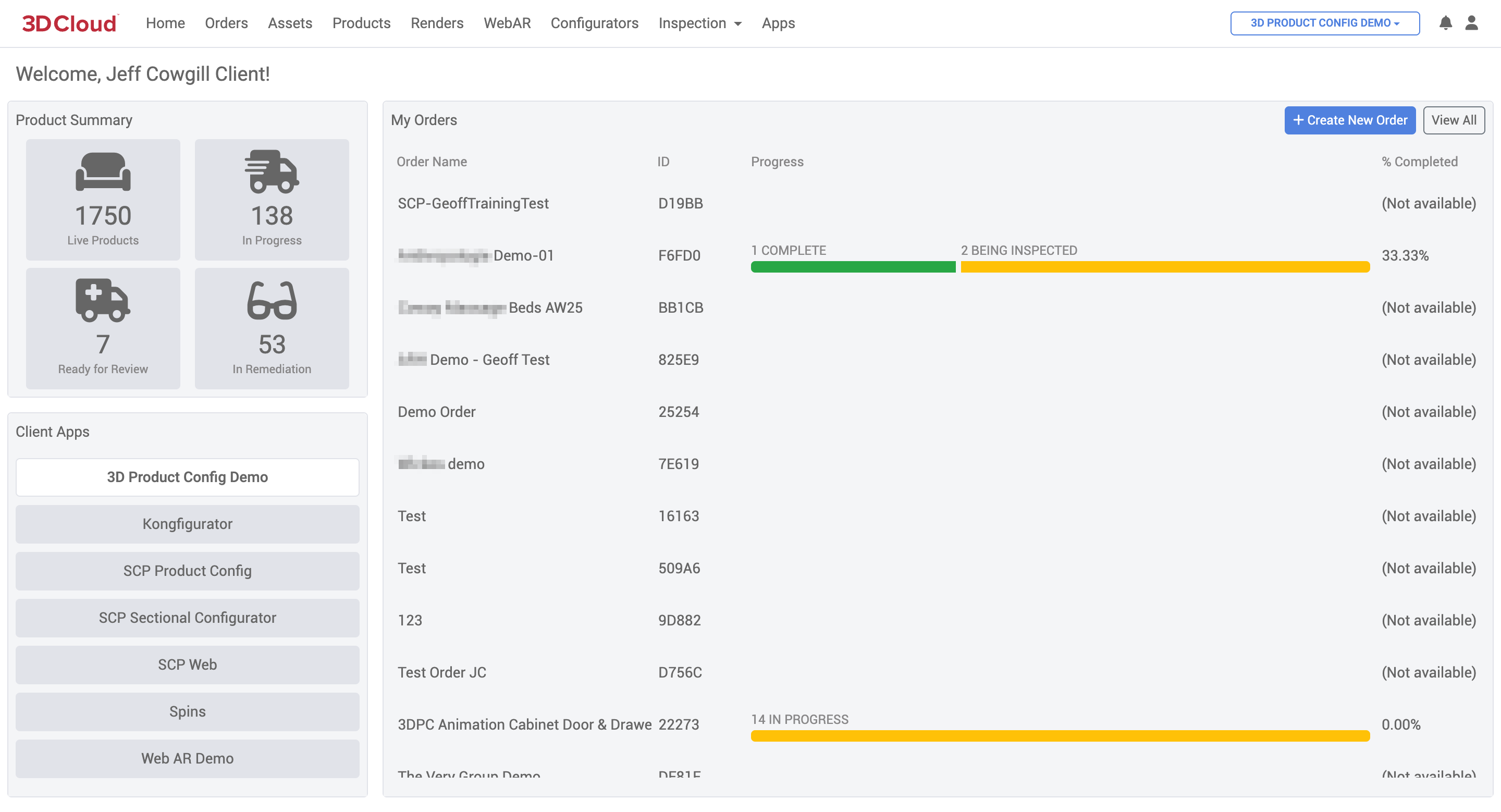
A
header barwith 3D Cloud logo, navigation bar, application selection dropdown menu, a notification bell and profile icon. From left-to-right:The
navigation barextends across the top of the page and includes all the main sections and pages in the system.The
client application menushows the applications related to your account.The
notification bellkeeps you up to date with events within the system.The
profile iconallows the user to edit theme/visual settings and profile information. For admin users, the ability to edit users and permissions is provided here.
Lastly, the primary main section appears below the header bar. In the screenshot above, the
Homepage is shown, with the ability to view a summary of products, orders and manage Client Apps.General Layout Troubleshooting
If you do not see a specific tool in the navigation bar or client, it probably means you don’t have the correct permissions. Reach out to your department lead to assist here.
Client and Client Apps
For 3D Cloud associates, the Client section is entered by clicking on the client’s logo/tile. The section manages a client, their applications (“Apps”) and the application configurations that enable them to operate. In order to view clients and apps, you must be logged in and have permissions to that client.
Client
A Client is defined as a company that has purchased 3D Cloud products or services and has an area specified for them in the 3D Cloud AMS.
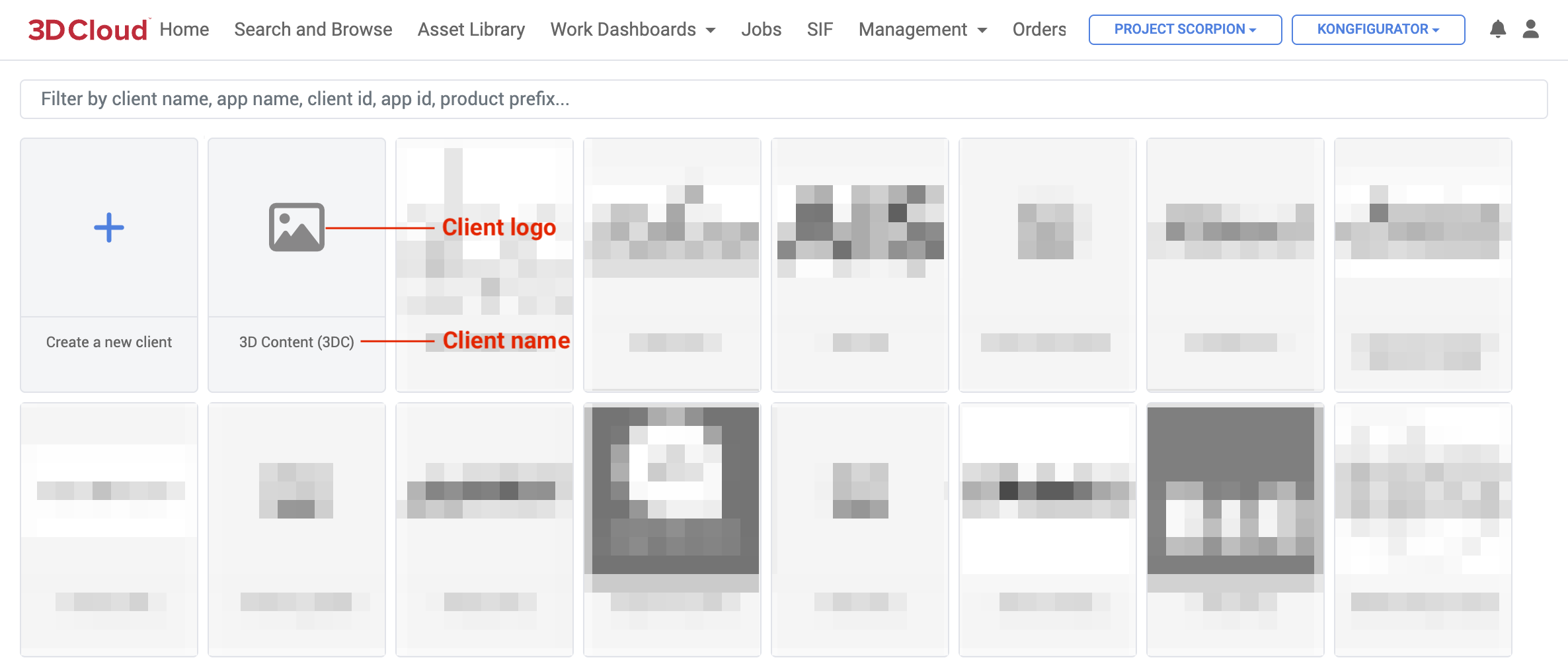
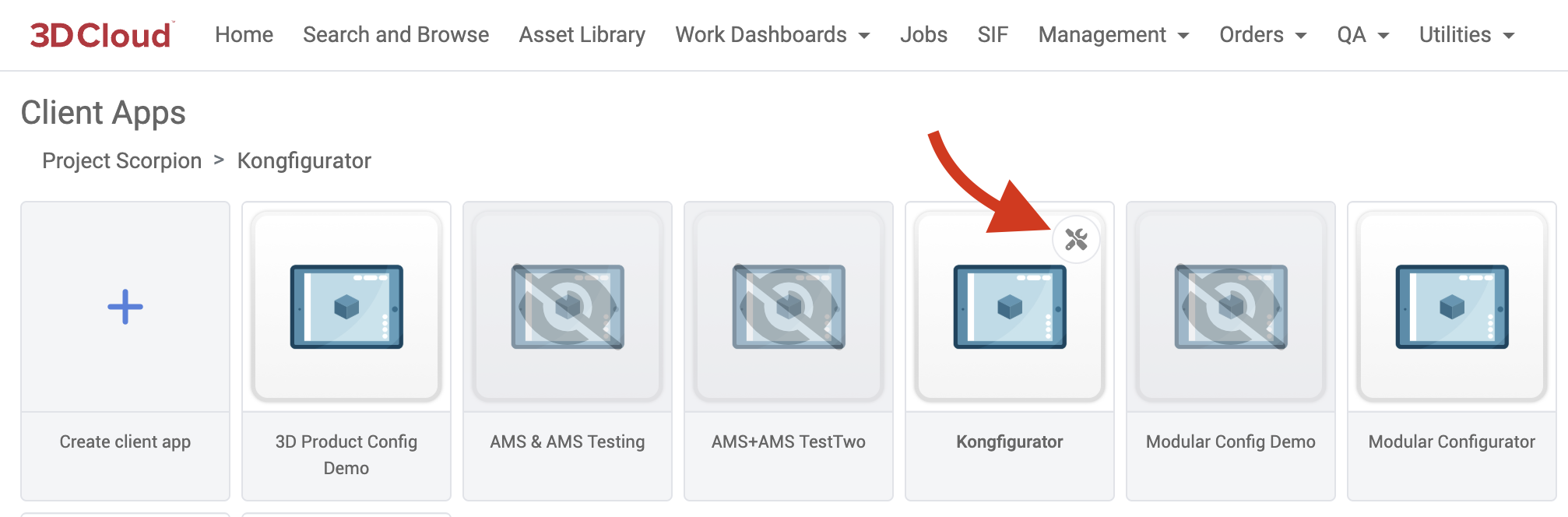
Clients are managed using the wrench icon in 3D Cloud under the Home section (list of all clients).
.png)
Edit Client
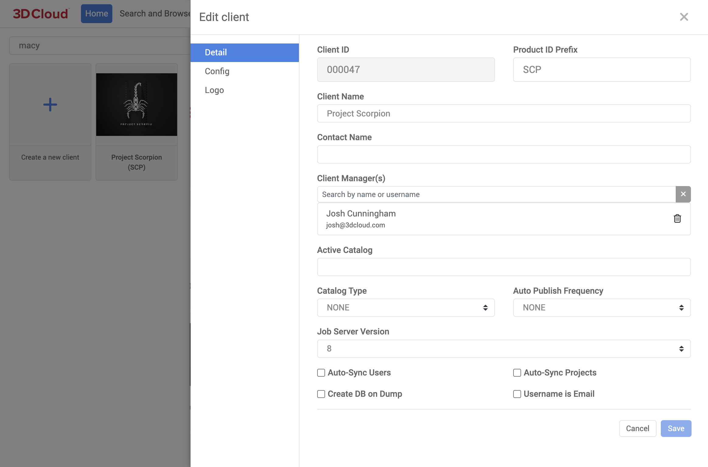
The Edit Client detail modal window lists general metadata about the client that can be edited.
Client App
A Client App (application) is a logical representation of a frontend application used by customers. Clients can have multiple applications, that may include 3D Spins, WebAR, Room Planner, Kitchen Planner, Deck Planner, Modular Configurator, Product Configurator or other API/PIM apps. Applications are managed using the wrench icon in 3D Cloud in the Home section after selecting a client.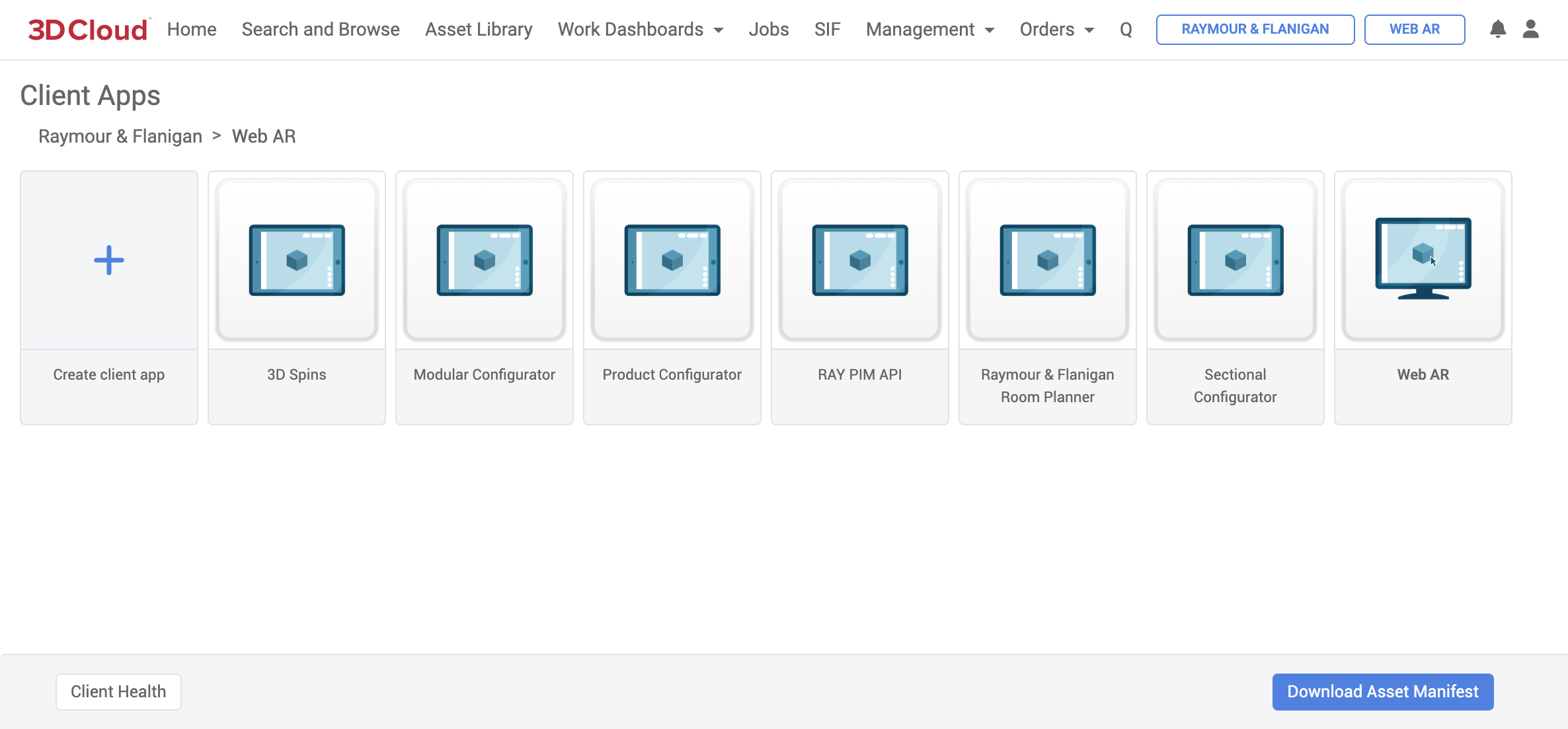
3D Cloud User: Apps Section displayed after clicking on Client tile
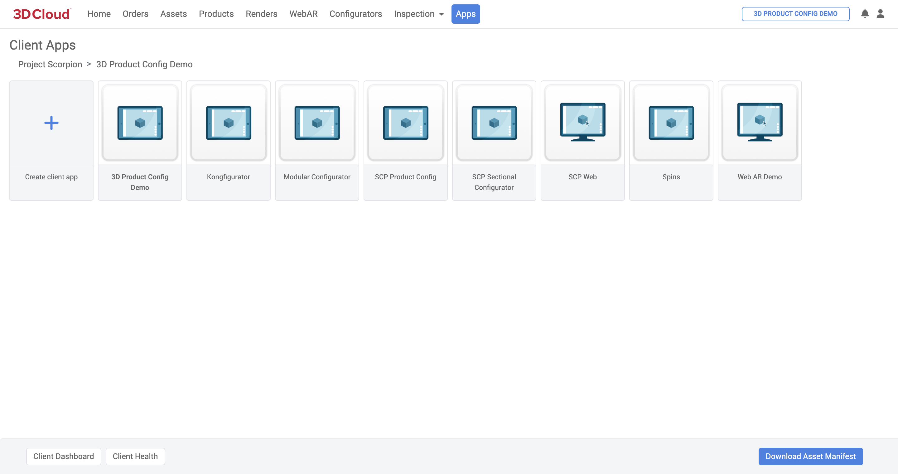
Client User: Apps Section displayed via “Apps” Navigation Bar
Edit Client App
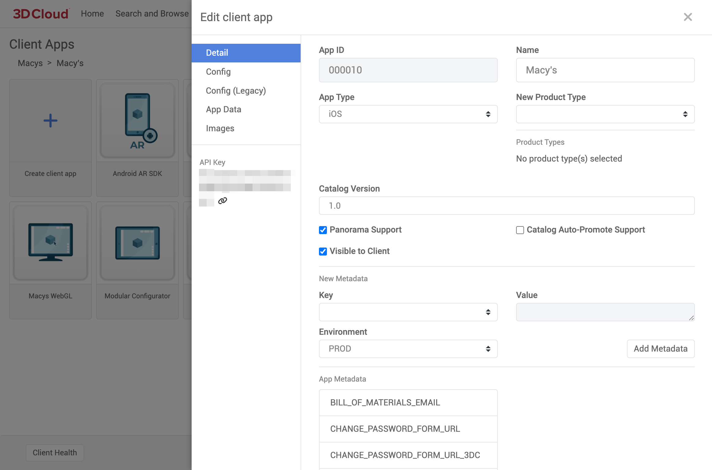
API Key
The API Key field shown is embedded into the front-end client application. This is used to access our APIs. These API keys get generated manually through a process defined by the AMS user.
Detail
Metadata Key Details
Config
Client App Config is application-specific metadata used to setup, configure, or customize an app. This metadata can be edited in its raw JSON form using the Client Editor in 3D Cloud (note: you must have client edit permissions to modify this data).
Saving a New Client App Config
After client selection, click on the Edit (wrench) icon on the top-right of the client app card to open the app editor, then select the Config tab.
You can load an existing Latest/Staging/Active config file into the editor, or start fresh. To download any of these files to your machine, click the filename of the configuration. Client app config must be supplied as a JSON string.
Saving as Latest will publish the config to the selected application’s asset manifest, making it available for development.
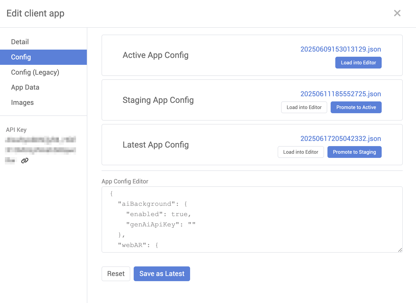
Promotion to Staging/Active
Once a Latest app config file has been generated, it can be promoted for use in the Staging and Active environments. Under the Latest App Config card, click the “Promote to Staging” button to promote the current latest file to staging.
Similarly, the “Promote to Active” button under the Staging App Config card will set the current staging file as active.
Config (Legacy)
.png)
App Data
This area defines application data. The main driver of this is having attributes tied to different application versions without creating a new app. For example, you can have a version of the app running 4.1 processing models with MMP in version 7. Alongside that, you can spin up a new version of the app running 8.11 and processing models using version 8.

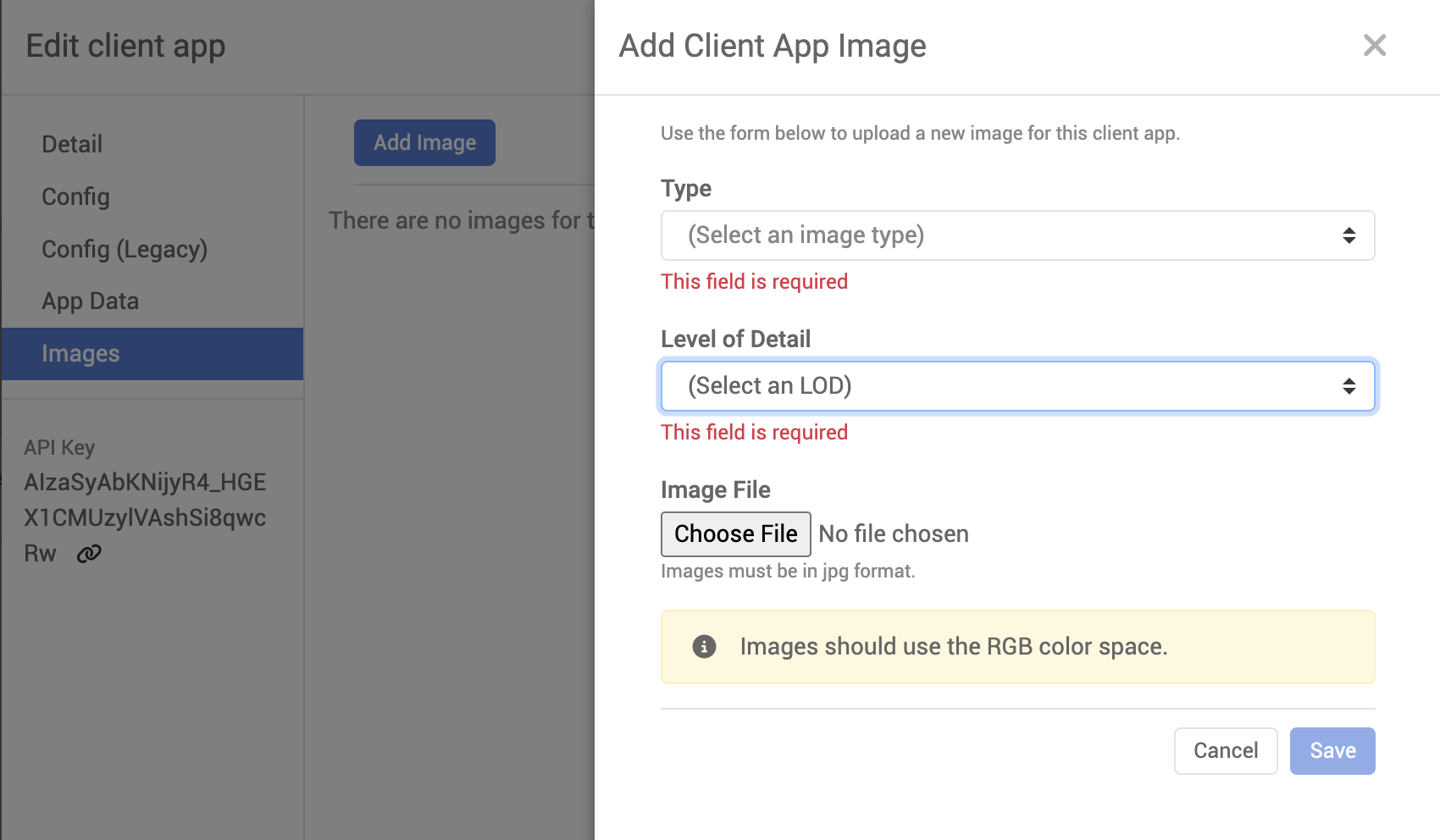
Images
You can upload a thumbnail image to represent the App in the AMS. Click the Add Image button to initiate the upload. Make sure the image is of high quality and in a suitable format (e.g., JPEG, PNG Minimum Size - 600x1200 px). The image should be in landscape mode for best results, as it will adjust to the size of the display or browser window
3D Cloud Create API Key
You can create client app API Keys directly inside 3DC. This process will also create Firebase Projects for the client app (see below).
All API Keys generated in this fashion have 3 API’s enabled: Discovery Service, Analytics and Marxent Client Services
To create an API Key:
Go to 3D Cloud AMS and select a client. This will bring you to the client app selection page.
Select the settings icon to open the Client App settings page
On the left hand side of the slide-out, select the Generate API Key button.
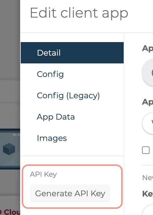
You will see a progress spinner with a status indicating the progress of the generation. This is running a job in UJS (
client-app-setup).Upon a successful creation, you will see the API Key in place of the generate button.
.png)
Firebase Projects
Firebase projects will be created for the client apps from this process. There are some key points worth noting:
Firebase Project ID’s follow this standard: env-client_id-app_id ex. test-999998-000041
Project names are derived from 3dc app name + environment.
Example: 3dc App WLA-WebGL will have 3 firebase projects named:
WLA-WebGL prod,
WLA-WebGL cert,
WLA-WebGL test.
(There is a maximum project name length (30 characters), so if the 3dc app name + environment will be too long, the 3dc app name will be cut off to give space for the environment.
Hosting
While the API key creation process does most of the set up for a client app, custom domains will still need to be created manually. Request these updates via Jira Service Desks.
Search and Browse
Search and Browse (accessed via the “Products” section in the Client view) is a way to search for virtual products in the 3D Cloud AMS.
A virtual product is identified in the 3D Cloud AMS by a unique Product ID (PID), which is typically the 3-letter abbreviation of the client in our platform, appended in front of the client SKU.
The products may be assigned to specific categories that reflect how the products are organized for front-end applications. Categories (and categories within categories) have parent/child hierarchies.
Note: If you do not see categories or products, make sure you have selected a Client first.
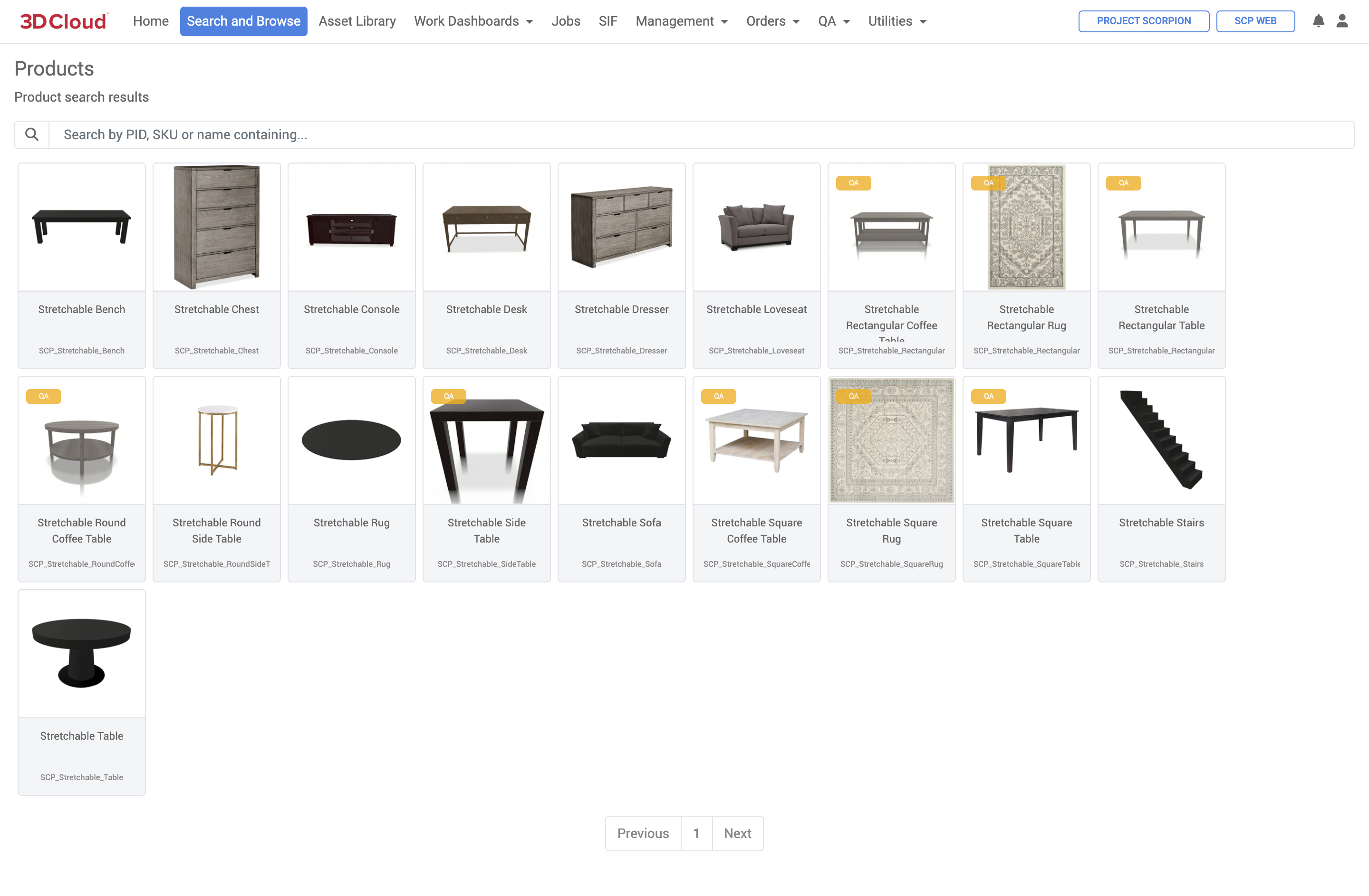
Search and Browse: Accessed via the Products section (Client User)
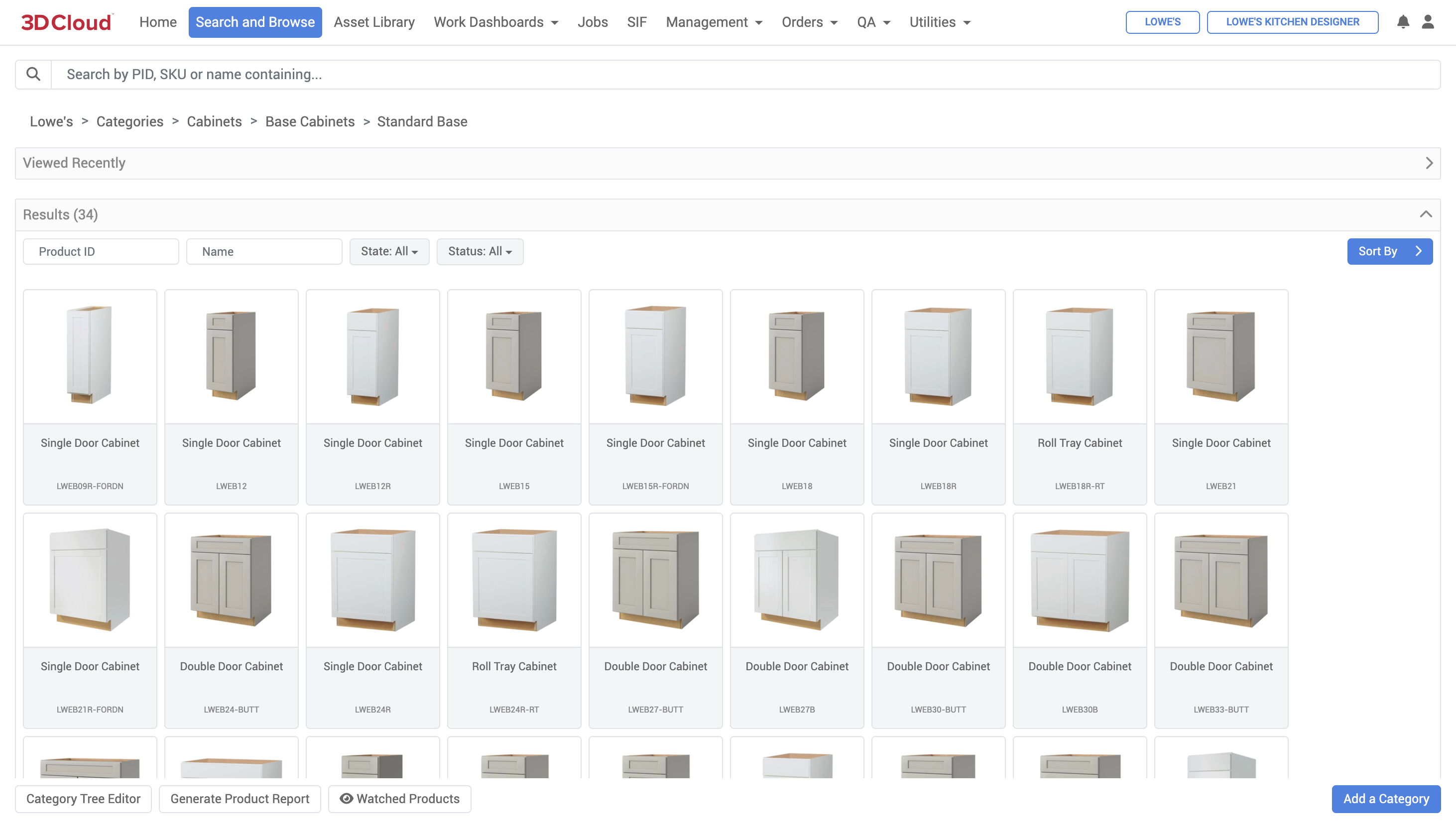
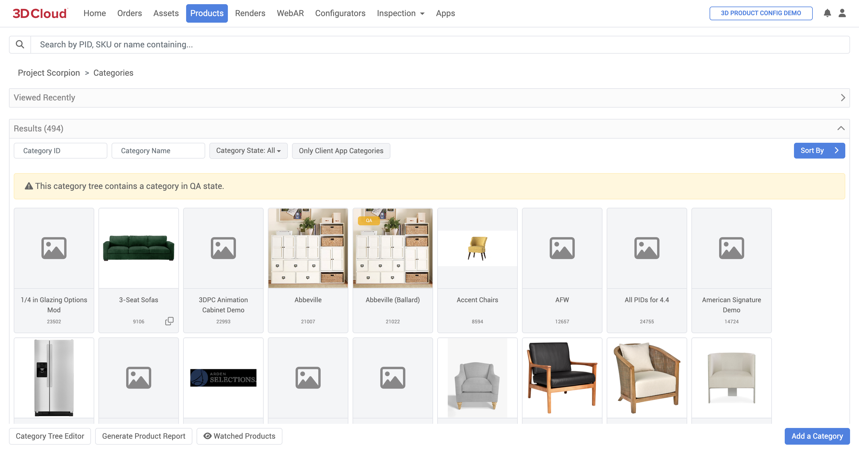
Search and Browse (3D Cloud User View)
The page is laid out to organize products within categories as stated earlier. Note some key areas starting from top to bottom:
On the header bar, note the
ClientandClient Appthat have been selected. All categories and products belonging to that client are listed.
The top Search bar can help filter things you are looking for:
Products by Product ID (PID)
Products by SKU
Products by name containing words

A breadcrumb showing you the depth of the nested category tree you are in.
![]()
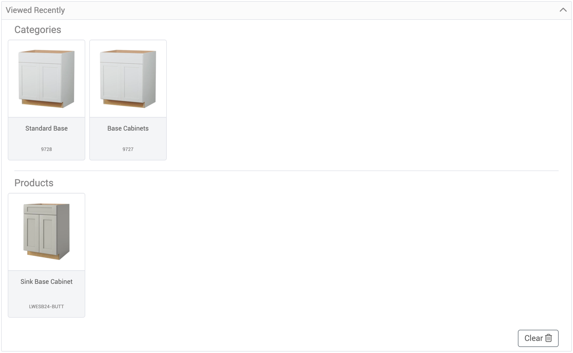
A section for recently viewed products for quick access appears in a collapsable section.
The
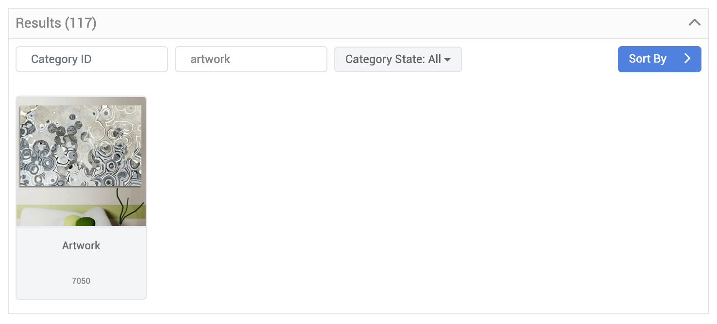
Resultsview shows the categories (default or search results) asCategory Tiles. Additionally there are options to:Find by Category ID
Find by Category Name
Filter by category
state(ALL, INACTIVE, ACTIVE, QA)Toggle button to show Only Client App Categories
Various
Sortingoptions (example: Sort by Category Name)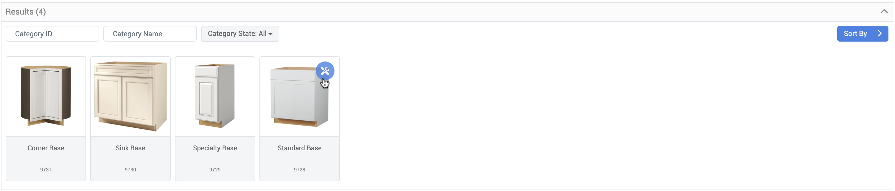
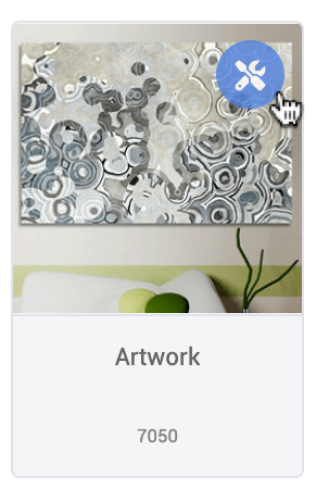
Category tiles contain:
A thumbnail (if set)
A configuration menu (on hover) denoted by the Wrench Icon
Category Name
Category ID
Navigating inside a category will present nested categories and products
Generate Product Report
At the bottom of the Search and Browse page, there is a Generate Product Report button.
Note: The “Generate Product Report” button is contextual to the currently-navigated category. If you navigate down the category tree, or down through a client app menu structure, you’ll only be given the option to generate a report from that category downward.
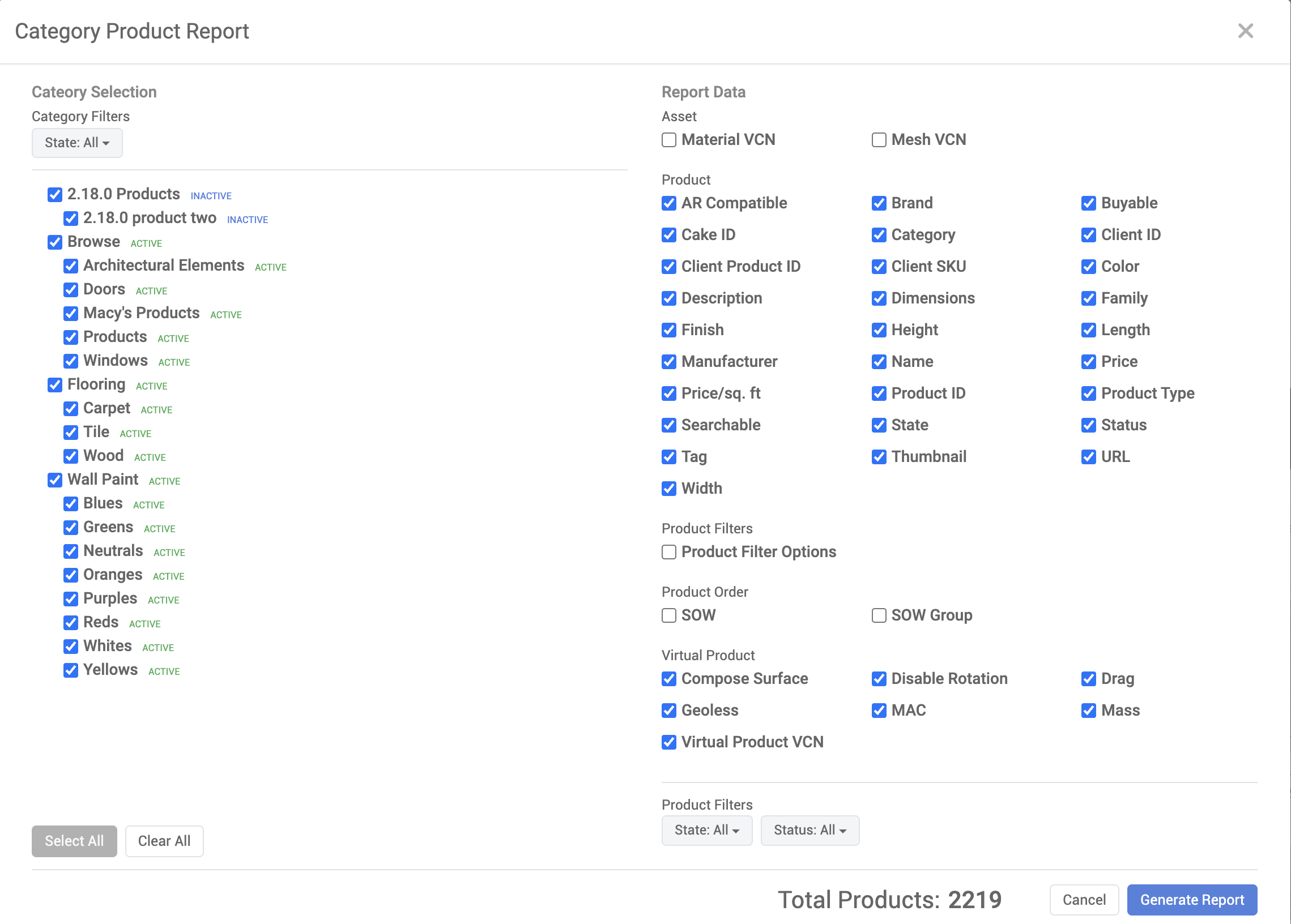
Select the Categories on the left-hand pane for which you’d like to export product data. Selectable categories can be filtered using the “Category Filters” selections. The exported products in a category can also be filtered by state using the “Product Filters” dropdown menus.
Select the Report Data you wish to include on the right. Only the fields selected on the right-hand pane will be included in the report.
Click the “Generate Report” button at the bottom right in the window.
An Excel sheet (.xlsx) file will be exported.
Note: The “Total Products” count will update on the bottom-right whenever category/product selections are updated. Note that reports containing a large number of products might take some time to generate.
Categories
A Category is a container for holding products with similar properties. Categories are typically created to reflect a client's product assortment, website or catalog. The use of categories in the 3D Cloud AMS creates organizational consistency between client apps, merchandiser information and 3D Cloud data and business analysts.
Categories are used to organize products. Typically, we try to use a structure similar to the one the client uses on their website.
Categories are APP LEVEL - so if you have a Web App and iOS App - you’ll need to “duplicate” your category tree and have one iOS and one Web version.
Our category structure is set up in “tree” format. So the parent category that is linked to the menu is “Shop by category” and the children are: Dining Room Furniture, etc. There can be multiple levels of nested categories which is typical more with a wider product catalog. The number of category levels is not infinite.
We track categories mainly by Category ID - the unique identifier since sometimes (sub) categories can have the same name, while being in multiple top-level categories.
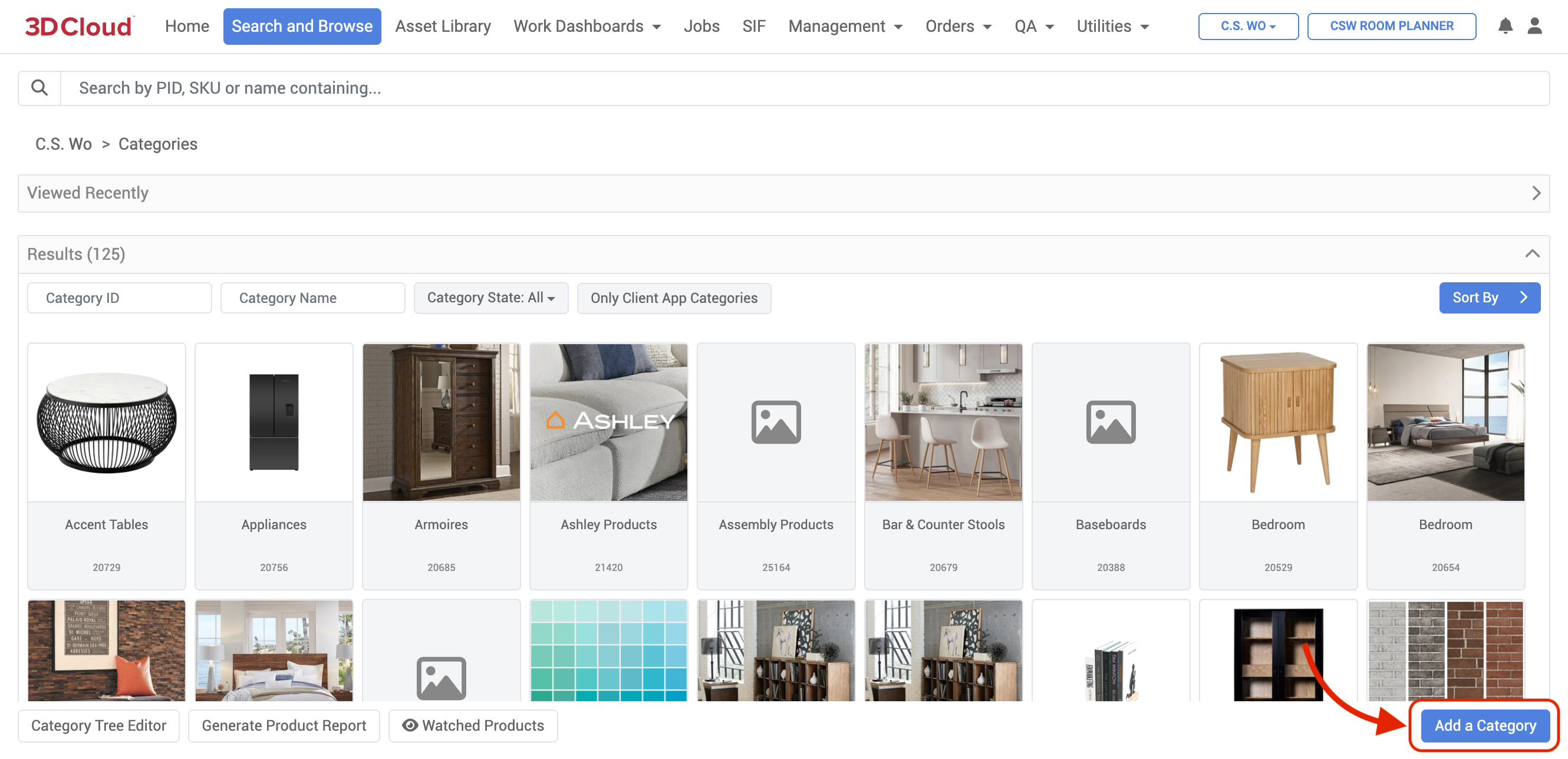
To view and manage all categories for a client, click “Search and Browse” in 3D Cloud
Prerequisites
In order to see categories, make sure you:
Have selected a Client
Search for a specific Category by Category ID or Category Name.
Creating a New Category
To create a new category for a client, on the home page of the 3D Cloud AMS, select a Client. Then head to the Search and Browse section.
Select the Add a Category blue button on the lower right
Fill in the form with:
Name: The name of the Category, for example, ‘Furniture’
ID: Leave blank. The Category ID will be auto-generated upon saving the Category configuration
Description: A short description of what the Category will house
State: The current state of the Category one of:
ACTIVE: In use by the client app
INACTIVE: Out of commission/deprecated
QA: For test use only
Weight: Integer value (lowest integer = highest priority) that determines the priority order in which the category is displayed compared to other categories at the same level in the Category Tree hierarchy. Categories are sorted for display by weight first, and then alphabetically for categories with equal weight.
Client App: Select the Client App(s) to which the Category should be assigned to
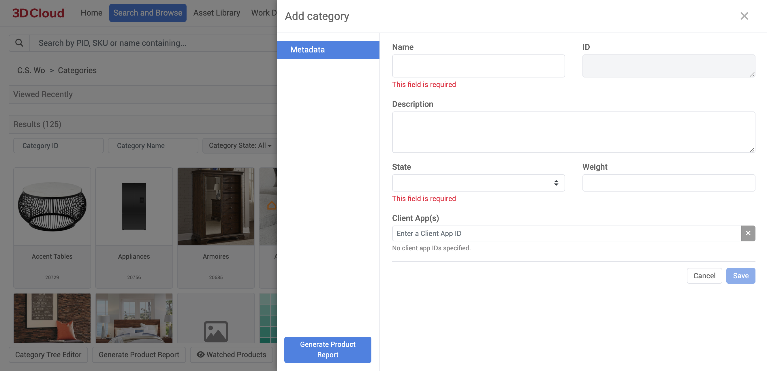
Save your category.
Editing Categories
A category can be viewed and edited using the wrench icon in Search And Browse.
Within the Edit Category menu, you can use:
Metadata
Thumbnail
Generate
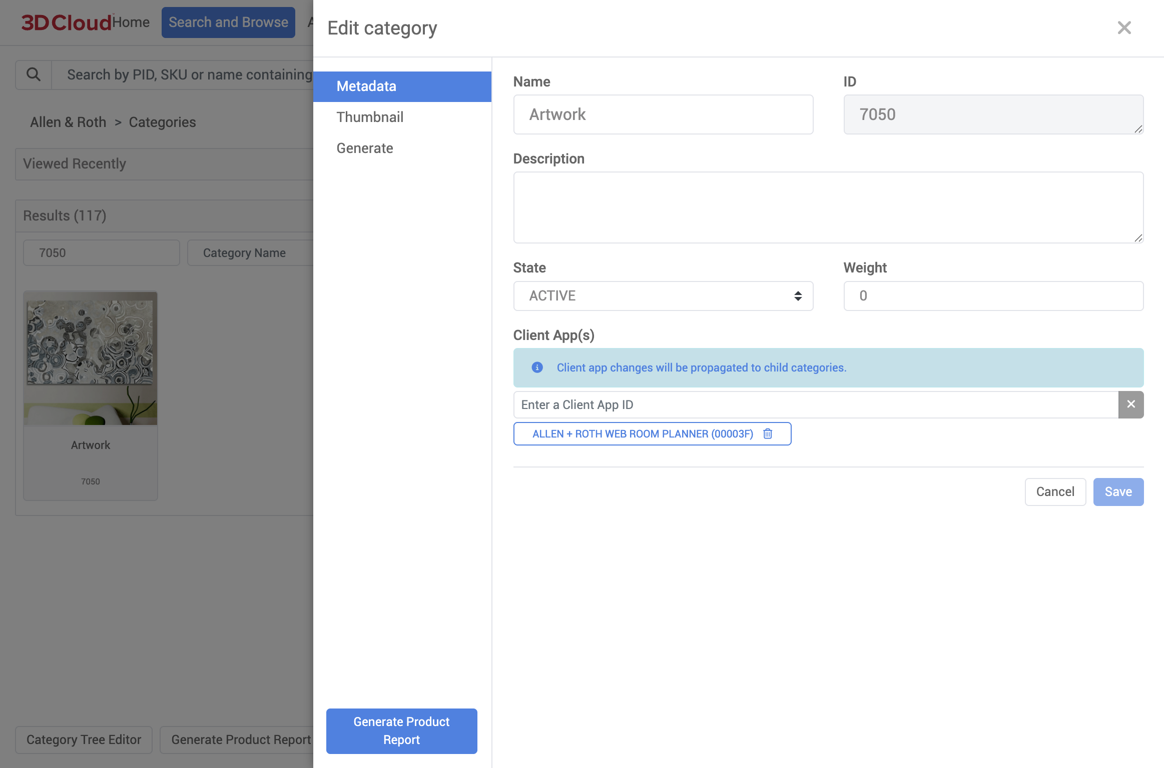
Edit Category: Category Metadata
The metadata section describes a category and it’s current status:
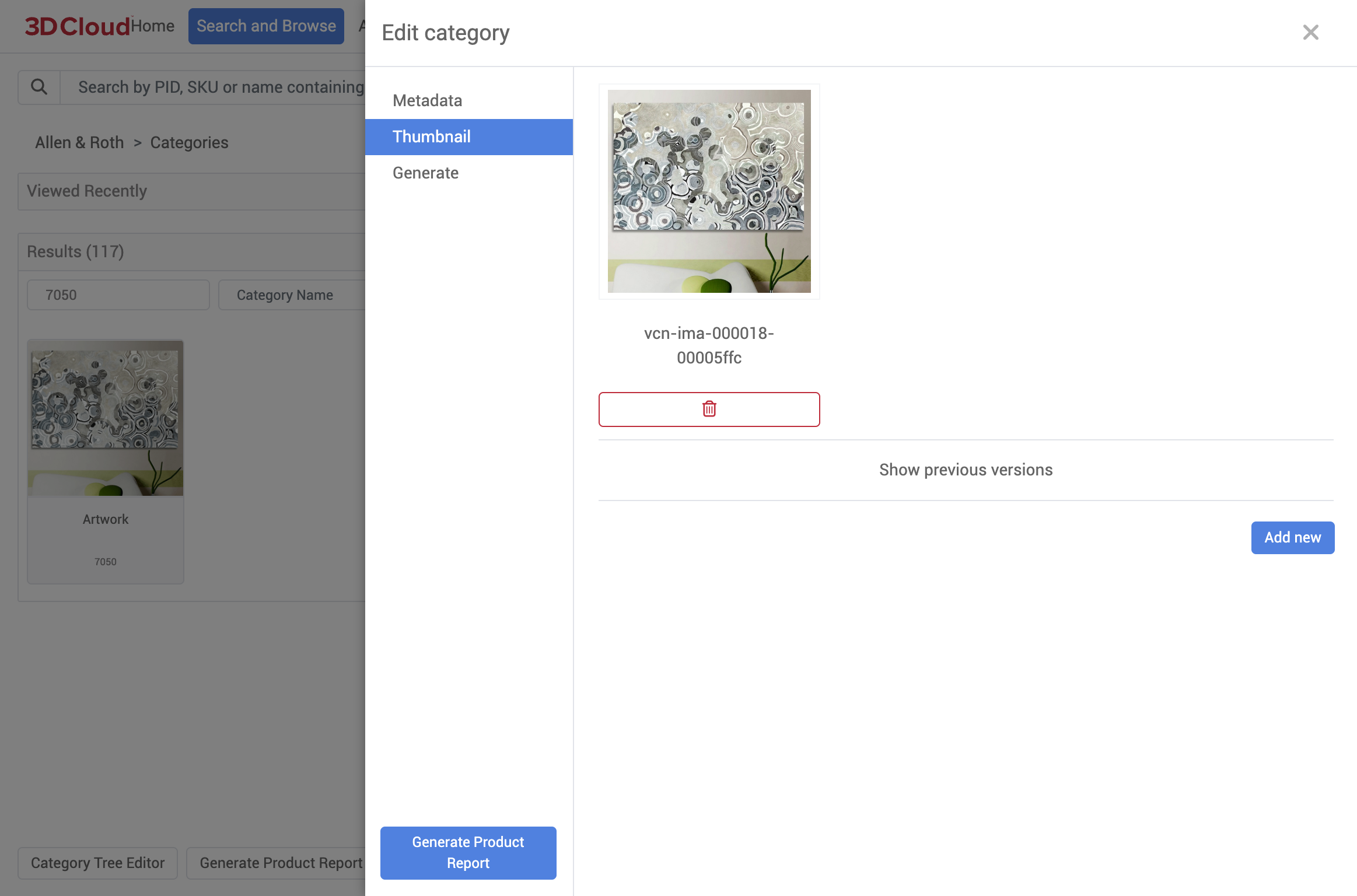
Edit Category: Thumbnail
Sets the thumbnail this category will display when viewed by the front-end application.
To add a thumbnail, simply select the Add new button.
To remove a thumbnail, simply select the red X button on the thumbnail.
To view the previous thumbnail versions, select Show previous versions.
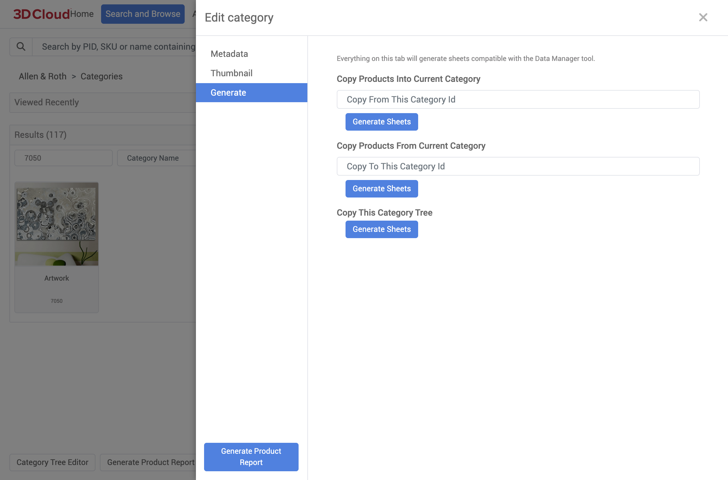
Edit Category: Generate
This section contains tools to help perform bulk operations on categories, like copying categories to another client, and getting a list of products within a category.
Category Tree Editor
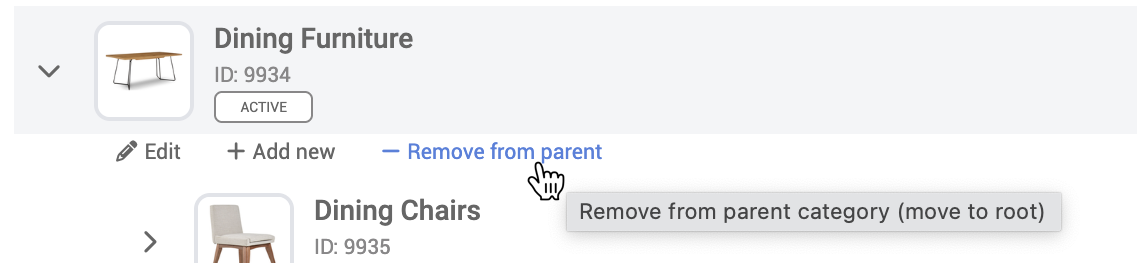
The catalog Category Tree Editor allows for the management of category relationships. Unlike the Search and Browse tool, categories can be removed from their parent as well as moved between levels of the tree.
Access the Category Tree Editor via the bottom toolbar of Search and Browse:
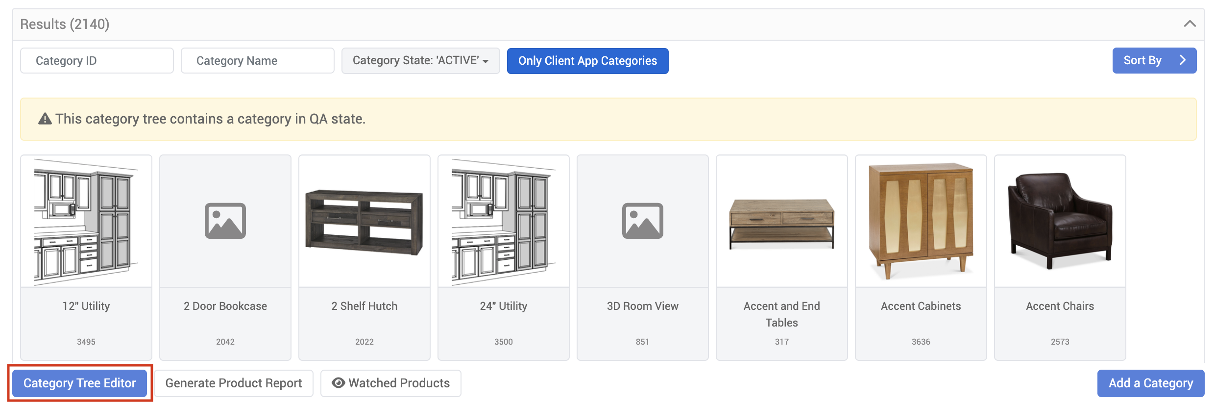
Note: The Category Tree Editor is contextual to the currently selected Client App.
Click the expand chevron (>) icon on the left-hand side of the category to view its child categories. New categories can be added to each level of the tree with the +Add new button, or at the top level of the tree with the Add Category to Root button (meaning the category has no parent relationship).
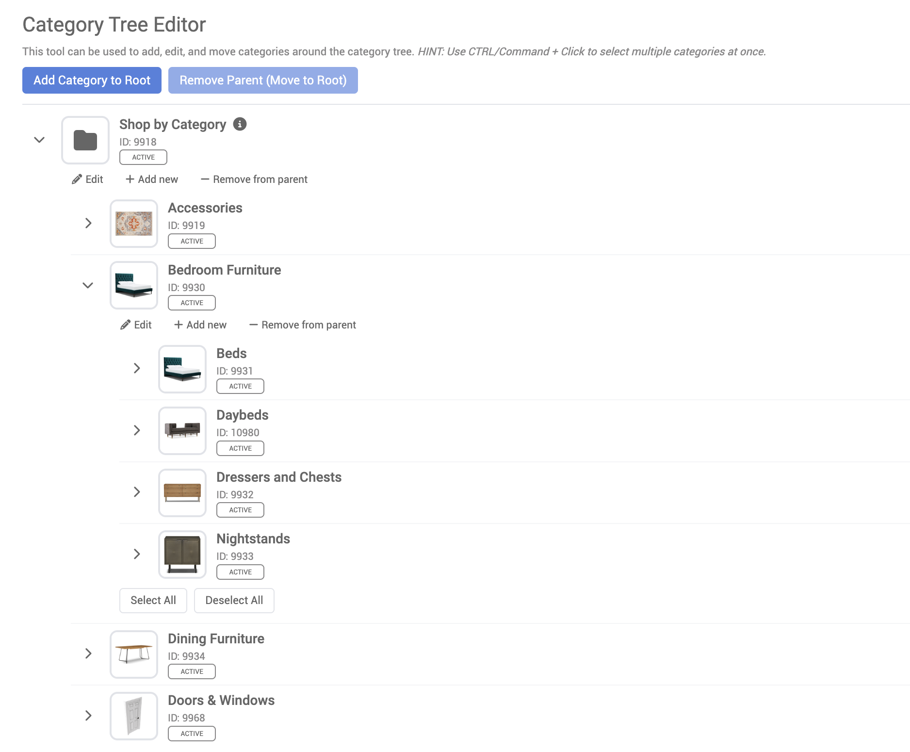
Note: An info icon beside a category name indicates that the category is assigned to a menu. Hover the icon to see the assigned menu name.
.png)
Moving Categories
Categories can be moved to different levels by dragging and dropping them to a new category in the tree, just like a file browser. Note that multiple categories can be selected and moved by clicking the checkmark icon on the right-hand side of the category row, or by CTRL/Command + Click multiple items.
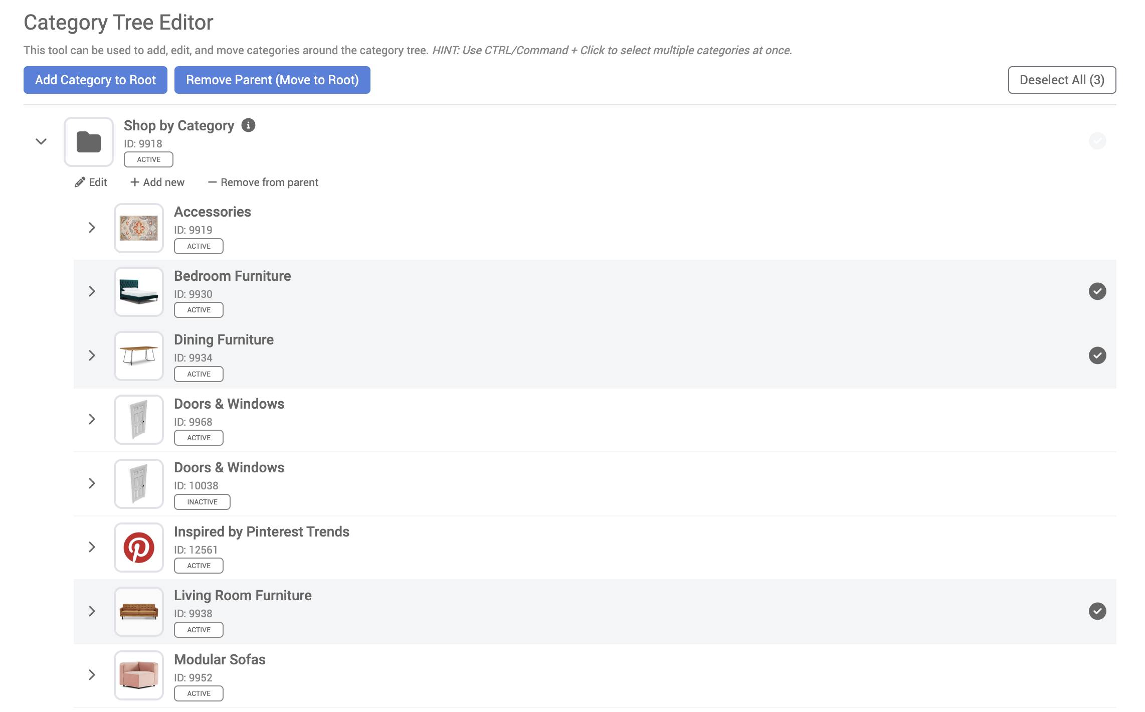
Categories can also be moved to the root of the tree, removing their existing relationships, by clicking the – Remove from parent button on the toolbar under the category name.
Products
Products are the lifeblood of the 3D Cloud ecosystem. They are the 3D representation of our client’s products. They range in complexity from a simple one mesh/one material product all the way to multi-mesh/multi-material products with complex business rules. Onboarding a new product and keeping it up-to-date is an involved process involving many departments and systems.
Products are used within our 3D apps, the 3D room planner, our 3D renders, Room visualizers, Web AR and 3D spins. The virtual products we create allow our clients to help their customers visualize the corresponding physical items they sell.
Adding New Products
In order to create a product:
Create a new Statement of Work (SOW) which is located under the Management section of 3DC.
Once a new SOW is created then create a new SOW Group within the SOW.
Create a product import sheet which allows the ability to import new products to the SOW group created.
After all the products are uploaded to the SOW group, add a reference file and spec to each one of the products imported. Then locked the SOW group that was created.
Lastly, open workflow and created an order, then place the order with the PIDs you want to be created
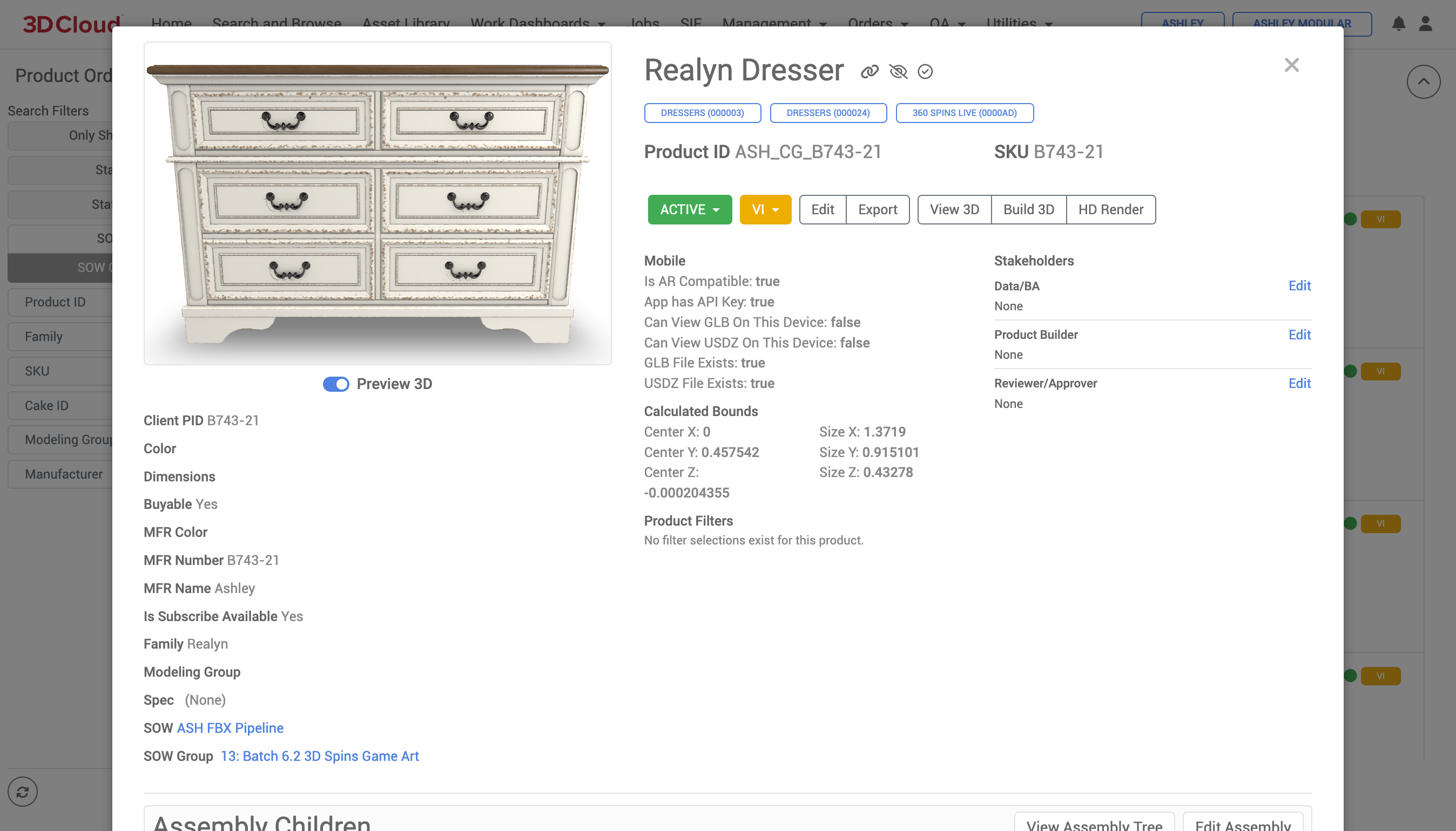
Product Description Page (PDP)
The Product Description Page (PDP) in the 3D Cloud AMS is the central detail page on any virtual product.
In order to view a product you must:
Have a Client selected
Navigate to a specific product page via Search and Browse
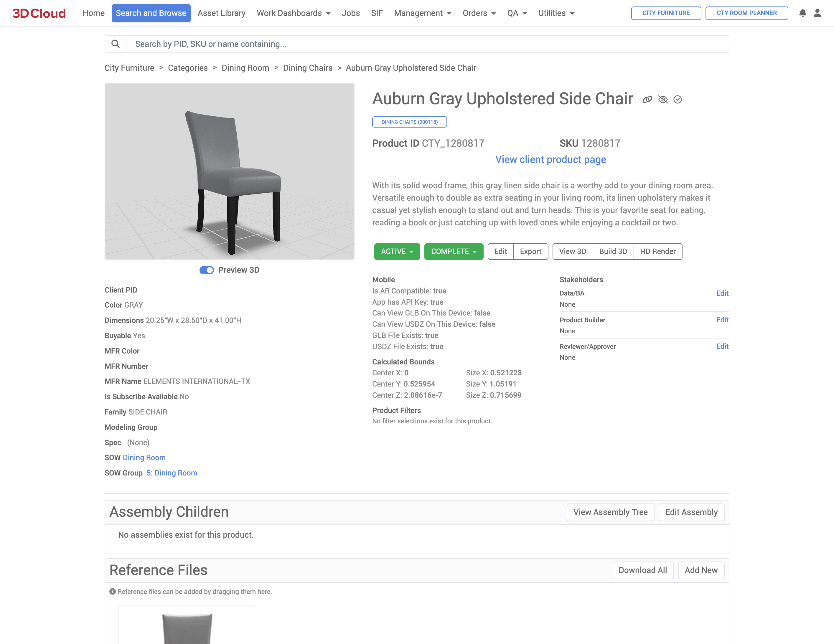
Some key areas to highlight within the PDP are:
The 3D Preview where you can visualize the 3D model in 360°
General metadata about the product
Name
Parent category
Product ID
SKU
Link to client product page (if available)
Mobile compatibility
Dimensions (Calculated Bounds) in meters
Status
Client PID
Color
Dimensions (WxDxH)
Buyable
MFR Color
MFR Number
MFR Name
Is Subscribe Available
Family
Modeling Group
Spec
SOW (with link)
SOW Group (with link)
Action buttons - Initiate various functions on the virtual product such as: Set Product Status, Edit data, Export source model files, View 3D (expanded view), Build 3D and HD Render
Assembly Children - The child products of this product (this makes up an assembly)
Reference Files - Typically images or PDFs describing the product and what it looks like or how it is used
History & Comments - Shows status changes of the product with date/time stamps
Set Product Status
There are two dropdown menus that can be used to set product status.
Product publishing state: Active, Inactive or QA
Product workflow status: Ordered, In Progress, Rejected, Failed, VI, Review_VI, External_VI, Complete
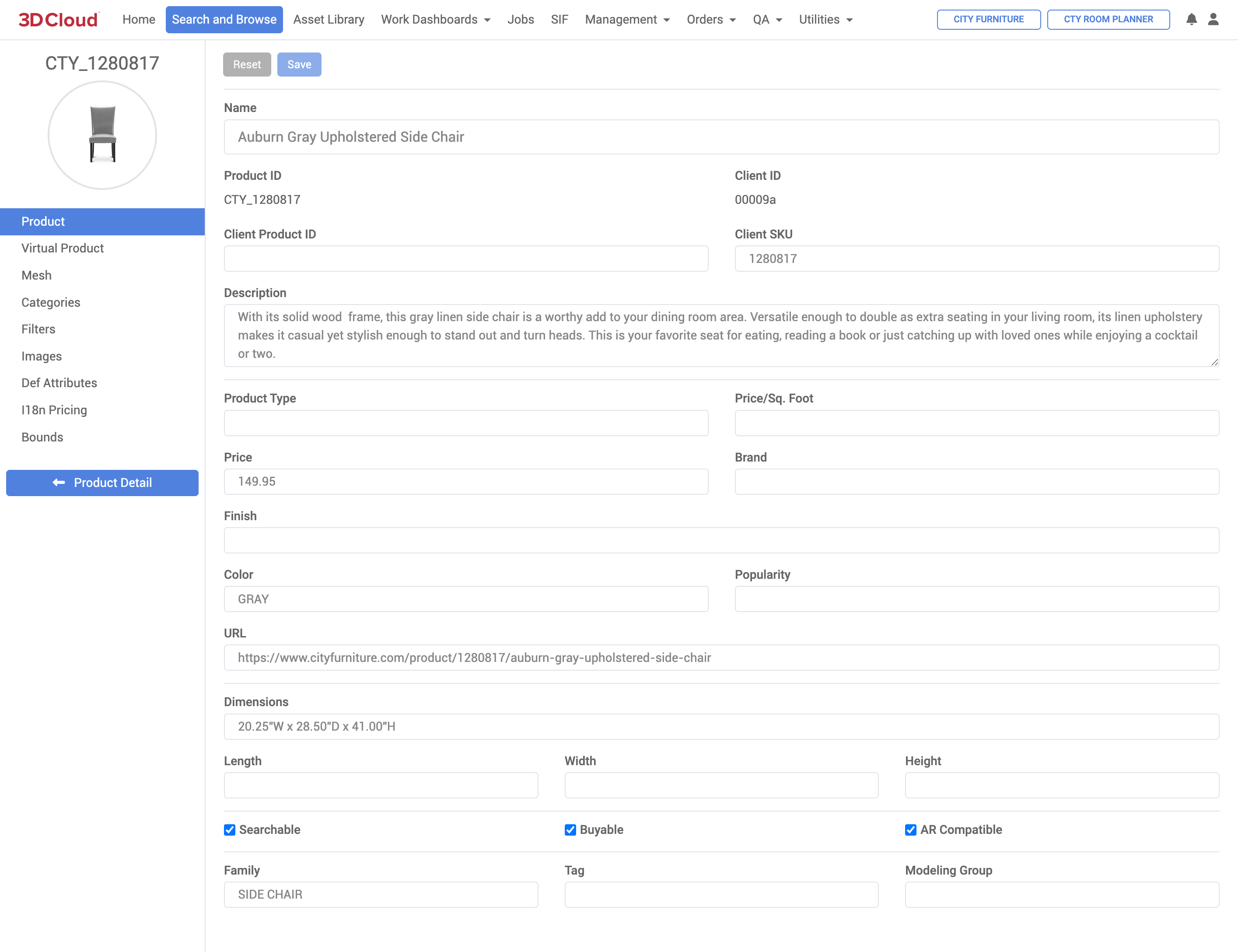
Edit Product
Selecting the Edit button will give you access to manipulate the product’s metadata.
Export
You can export a product’s 3D mesh and/or materials in various file types..
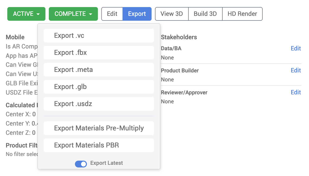
If an export type of .glb, .gltf, or .usdz has already been generated for the selected product, clicking the “Export .extension” button will automatically download the file. Otherwise, the generation will be scheduled. If the file needs to be generated, a job progress indicator will appear in the top-right corner of the application.
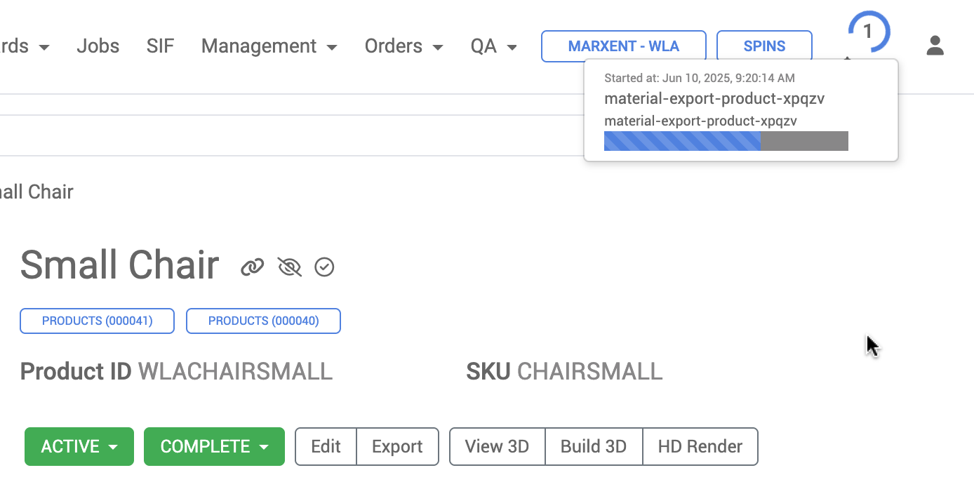
On completion of the generation job, a link to download the file will be made available by app notification.
View 3D
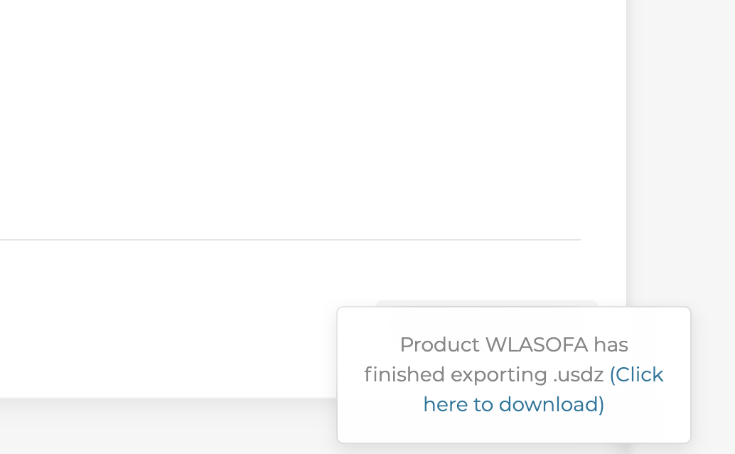
The View 3D screen enables the viewing a product in 3D. This screen is the same as the PDP 3D Preview, but with additional options and a larger, full-screen viewport.
Using the fly out menu (bottom right chevron icon) and selecting the wrench icon gives you a few options when previewing the product:
Preset camera angles
Camera free rotation and zoom (left-click rotate, scroll wheel to zoom, right-click pan)
Viewer “overlay” toggles:
Compound colliders
Model Space bounds (MSB)
Pivot Points: The point in 3D space where the object anchors to; also the point it rotates around (this is local to the object, not the world)
Mount Points: These are points where other objects can mount their pivot points to. Used for business rules.
Dimensions. Show dimension lines and units of measure for bounding box.
UV Checker (2 channels)
Asset Versions
Babylon Debug menu (toggle on the Babylon player default scene explorer and inspector control overlay)
To return to the Product Detail Page, click the blue “Product Detail” button in the lower right.
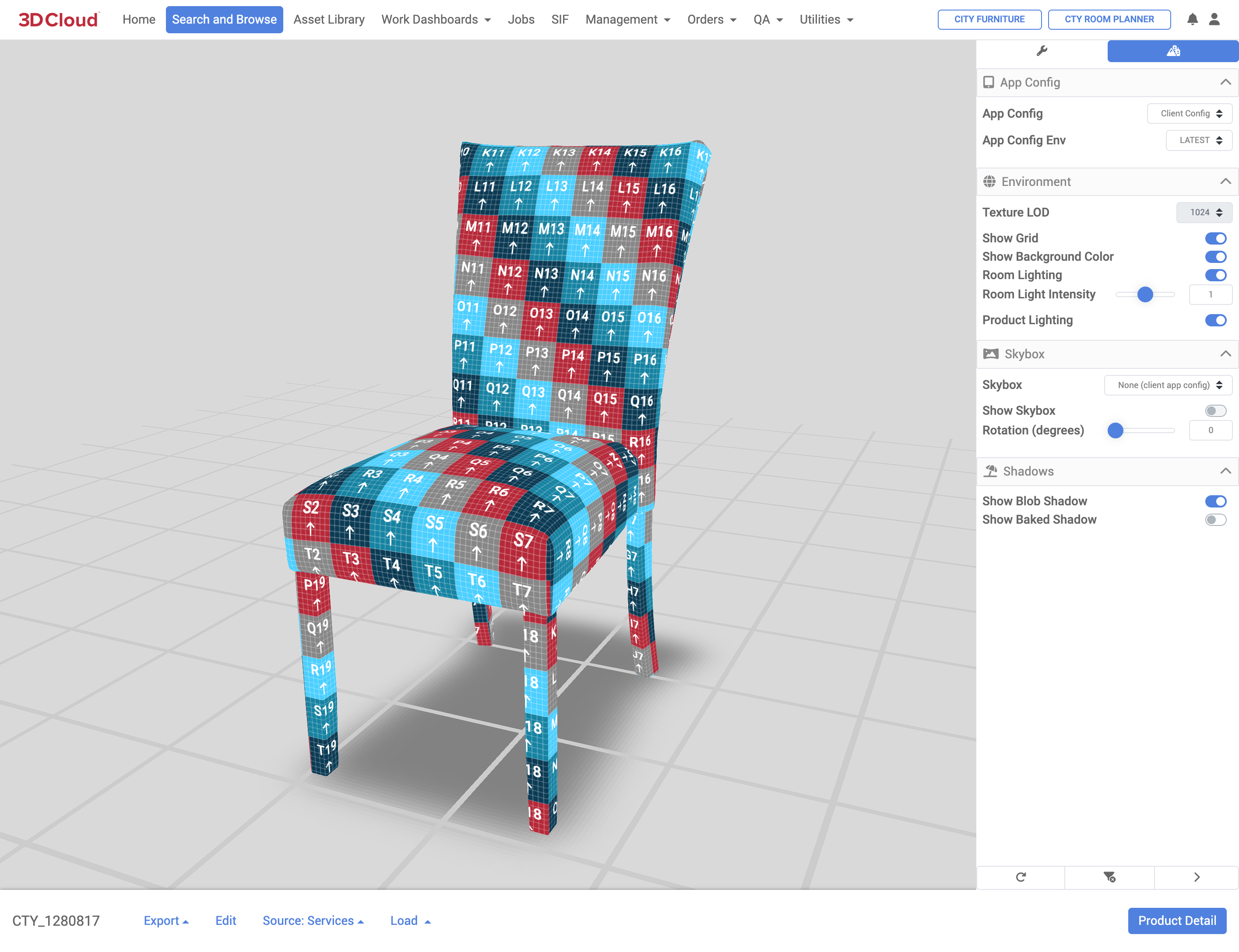
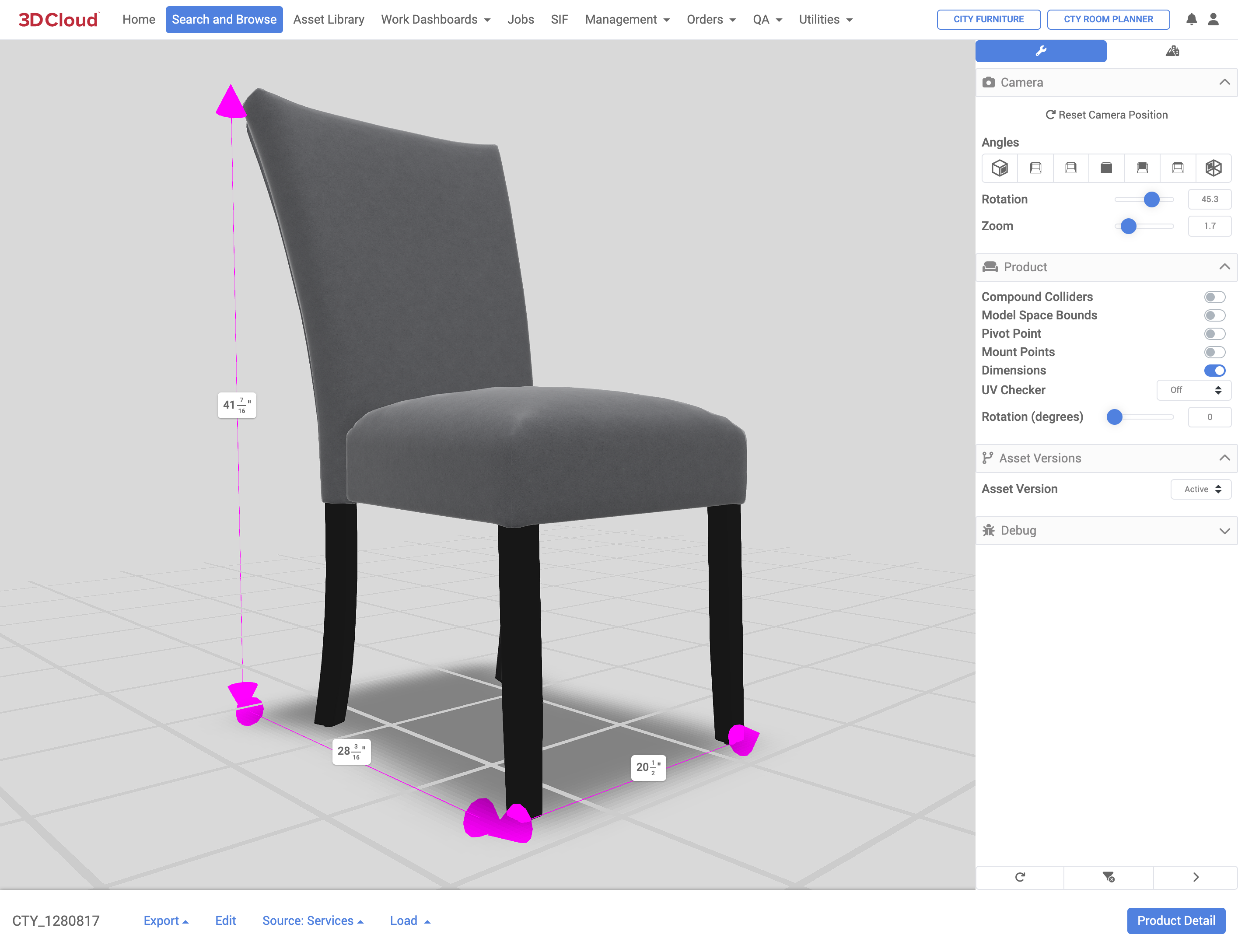
Using the fly out menu (bottom right chevron icon) with the mountain/city icon gives you a few options when previewing
Selecting the App Config and App Config Env
Selecting the Texture LOD (64, 128, 256, 512, 1024, 2048)
Toggling the environment (Grid)
Toggling Show Background Color
Toggling the room lighting
Setting Room Light Intensity
Toggling the product lighting
Selecting Skybox (toggle) and rotation
Showing Blob or Baked Shadows
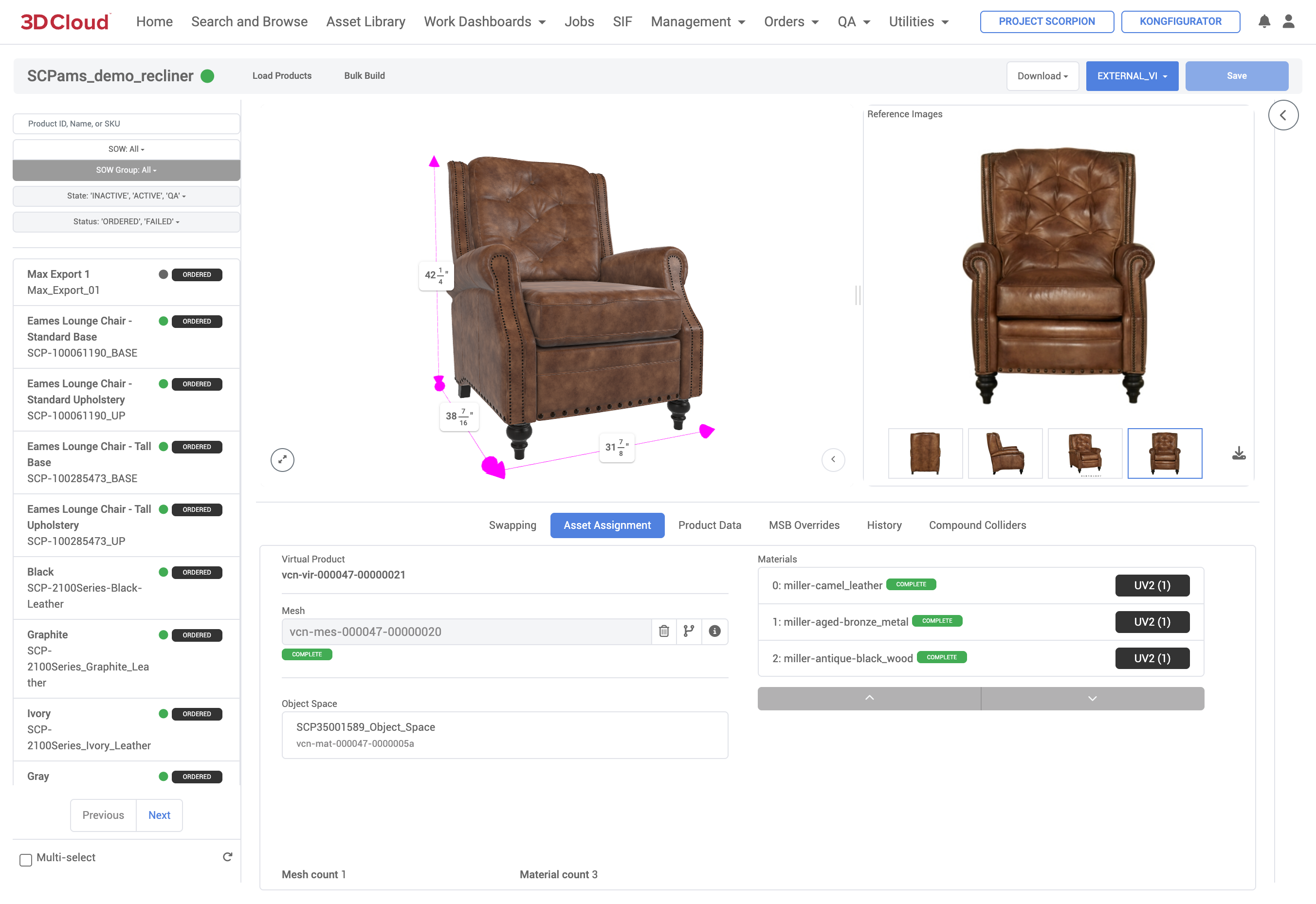
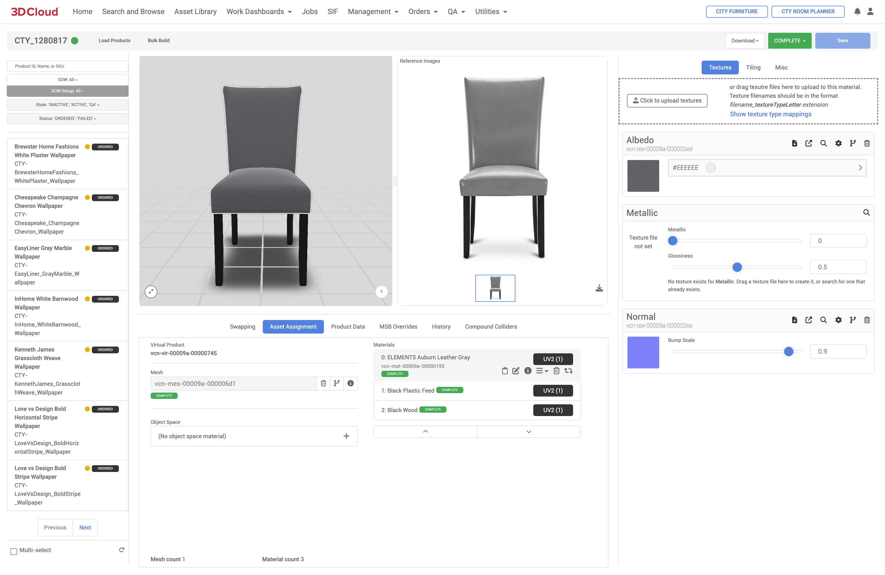
Build 3D
The Build 3D screen provides a side-by-side view of the 3D Product on the left and the reference images on the right. The page is used to create the important Asset Assignment of the Mesh and Material that make up the virtual product, a process referred to as “Product Building”. Here you can assign (add or remove) the mesh and materials, handle their versioning and preview the results.
The Build 3D screen also displays material Swapping options, Product Data, controls Model Space Bounds (MSB) Overrides, History and Compound Collider controls.
HD Render
The HD Render screen is where high-definition renderings can be generated, either one at a time (single product render), in bulk (via spreadsheet upload) and as 360° Spin renders (32 angles at 11.25° increments, plus the top angle).
Additionally, camera and product position presets, lighting, exposure, HDRI, background and shadow controls enable customization of the rendered image. For details on product rendering, see our Product Renderer section.
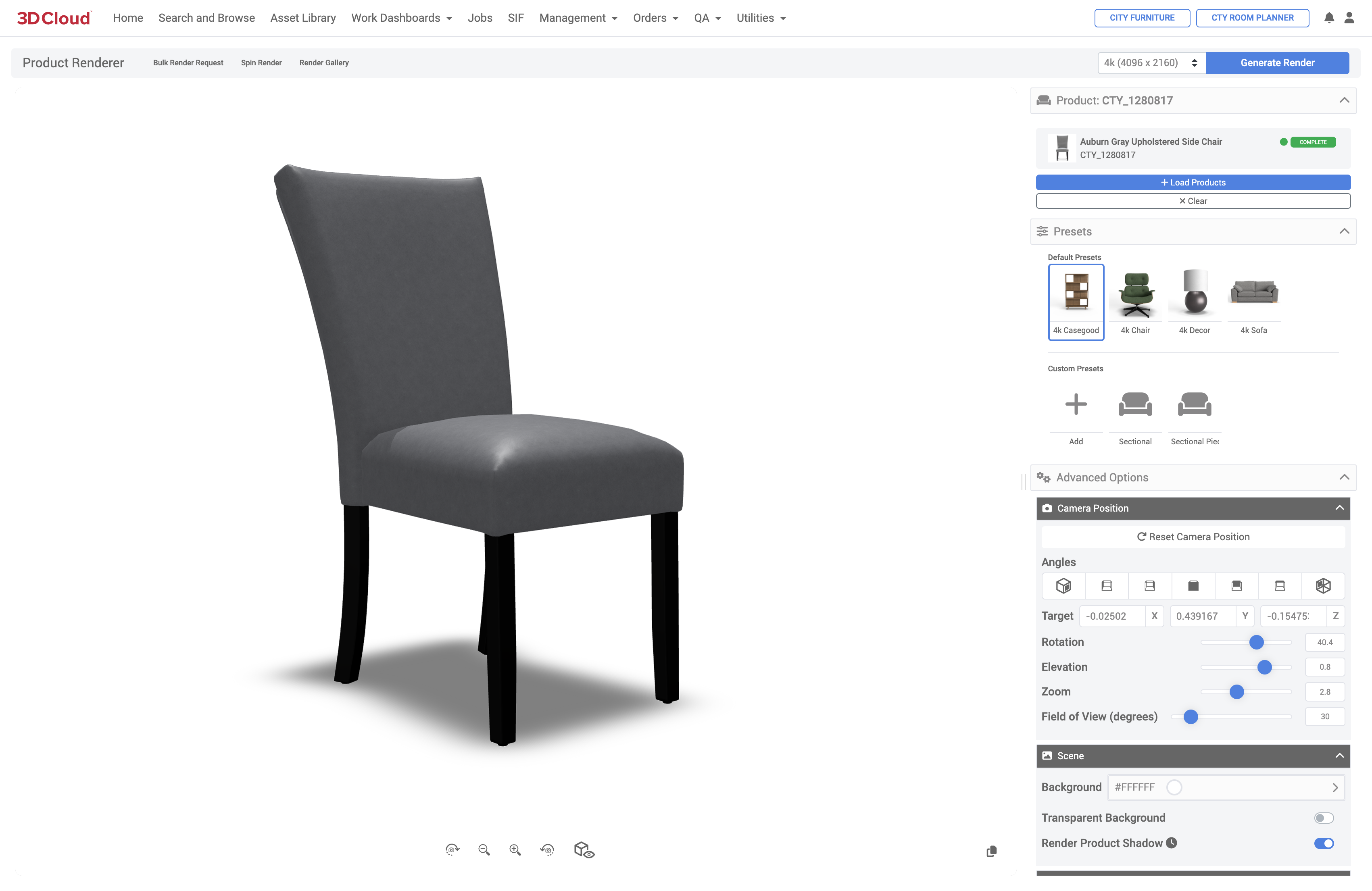
A Render Gallery area stores final render job images sorted by Date and Type.
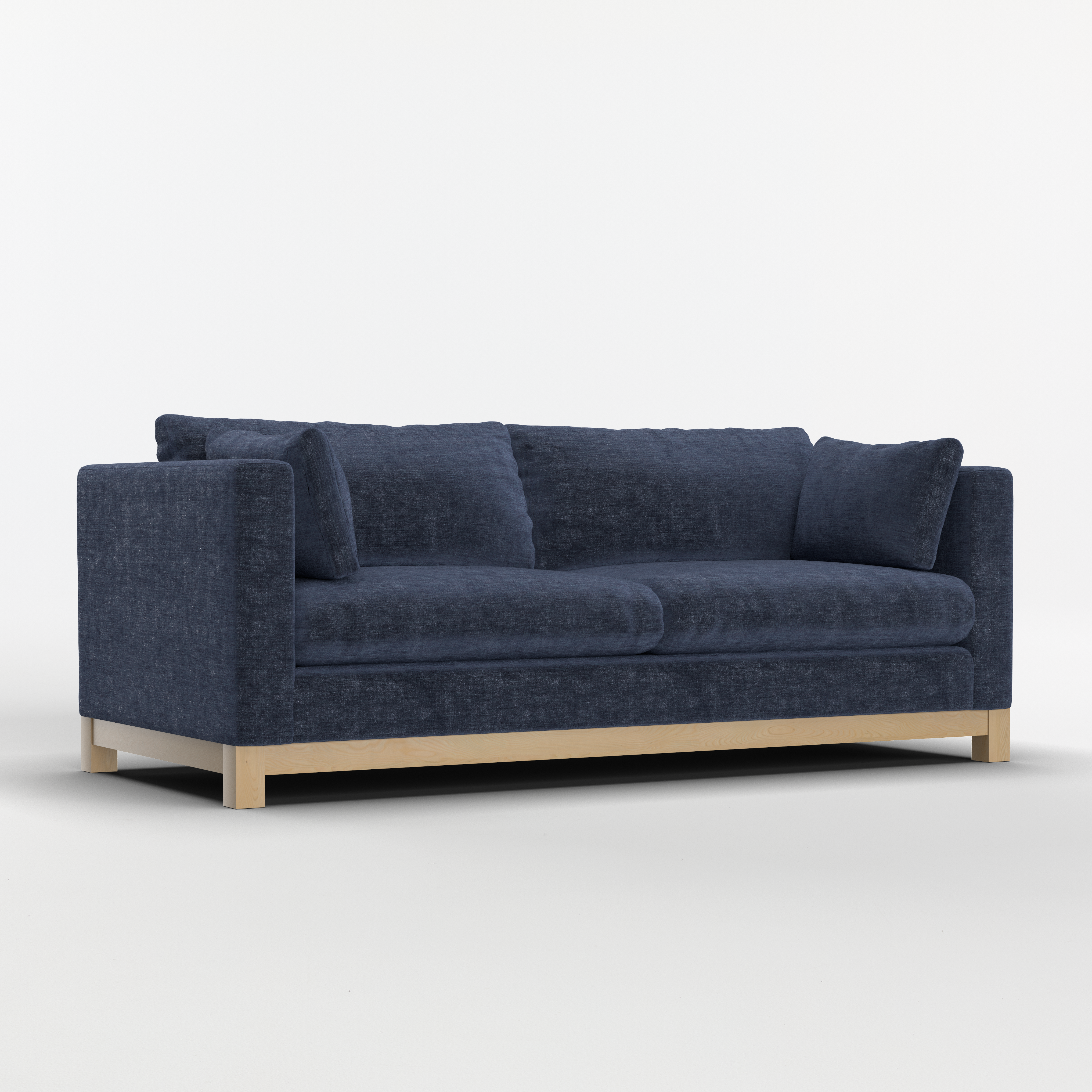
Sample HD Render
Asset Library
The Asset Library is a tool in the 3D Cloud AMS that allows you to search for assets, using a variety of search and filter options.
Assets are things like meshes, textures, images, and things that get attached to products and virtual products in the 3D Cloud AMS. Each level of detail (LOD), size, and format would become it’s own asset.
For example, a Mesh asset (3D model, also referred to as a “Geo”) may have LOD versions of 64, 128, 256, 512, 1024, 2048 and others. Mesh assets are most often uploaded to the 3D Cloud AMS as .fbx or .glb files.
Texture assets are files used in the process of building 3D Materials. Textures give Materials visual elements such as:
Color
Depth
Perspective
Detail

Example: Texture file that looks like a flat piece of wood, but can be wrapped around a 3D object when applied to a 3D Material.
An Image asset may be resized in to different standard image sizes and converted to different image formats. This means that a single image could have many different assets that are generated for it to accommodate size and format requirements.
Assets are used to store information about these meshes, textures, images, etc. and associate them to Products. These conversions happen within our Universal Job System (UJS) and are often automated so that once a mesh, texture, or image is uploaded to 3D Cloud AMS, it will kick off UJS jobs to generate whatever is needed for you.
Types of Assets and Visual Commerce Numbers (VCN)
In the 3D Cloud AMS, we create a unique, distinct human-readable identifier that all assets in the system get assigned upon creation (or upload). This identifier is called the Visual Commerce Number or “VCN”.
Depending on the type of asset, the VCN number will follow this naming convention.
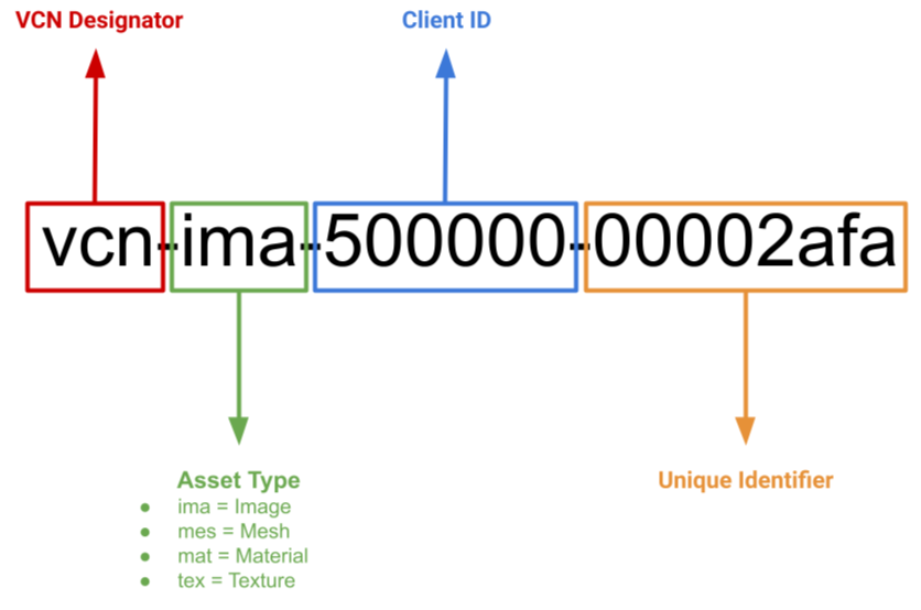
Examples:
Mesh: “vcn-mes-000001-00000001”
Material: “vcn-mat-000001-00000001”
Image: “vcn-ima-000001-00000001”
Texture: “vcn-tex-000001-00000001”
Image: ”vcn-img-000001-00000001”
The Asset Library View
By default the Asset Library will present the user with all assets, sorted by newest created first. Each asset will display its name, VCN, and current state in the upper left. If the asset has a thumbnail image, these will also be generated to view.
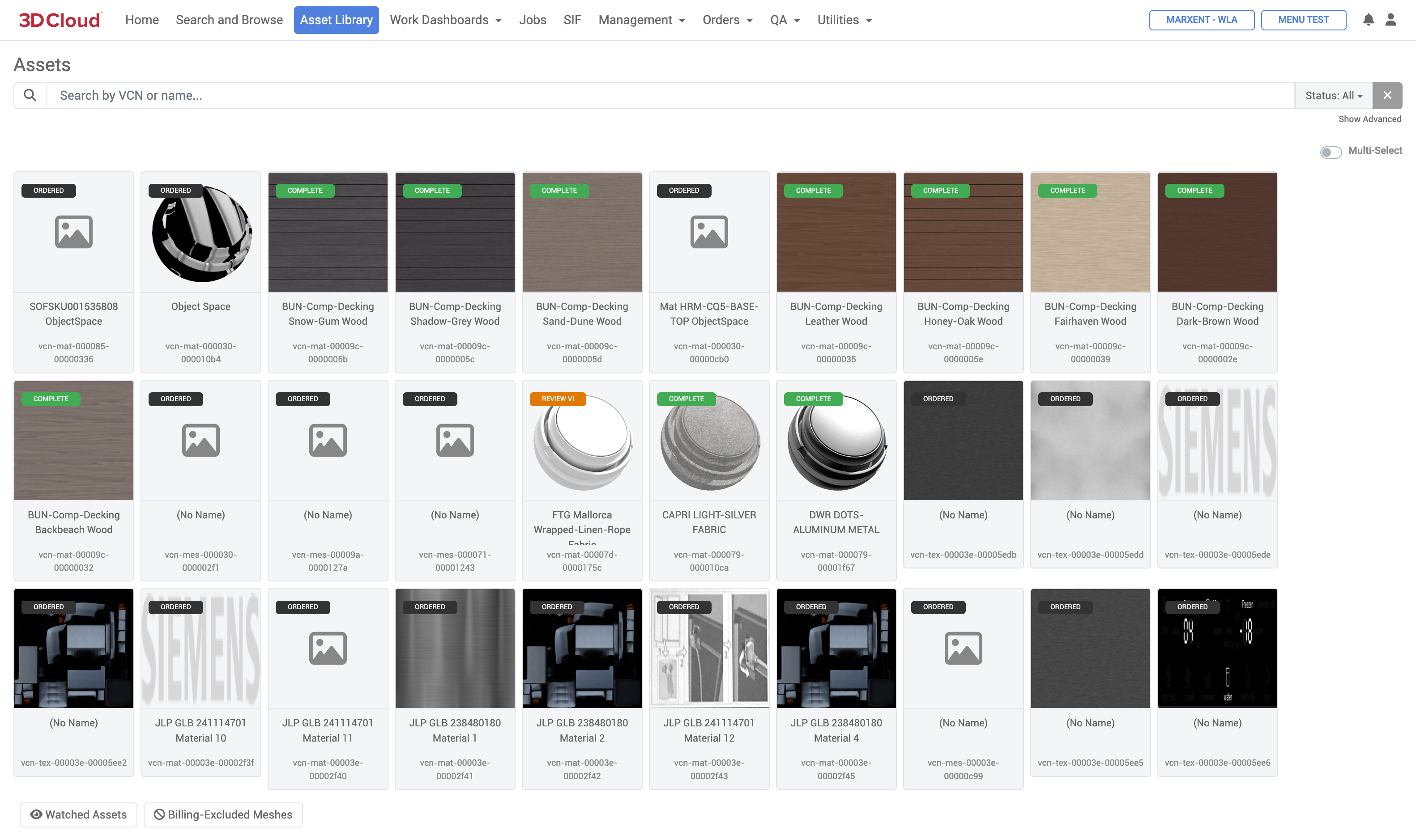
A user can search for particular assets by using the Search bar. The Search bar will search on VCN or Name. For a more granular search, you can use the “Show Advanced” filter options to pick certain Asset Types, SOW or SOW groups, Client, Family, SKU, Cake ID, or Manufacturer.
Additionally the Asset Library view can be sorted by Relevance, Last Updated or by Status.
Search queries that wish to be shared may be done by copying the URL generated in your browser, and shared. These URLs navigate back to the same search parameters that were used originally, and can be used to easily share searches.
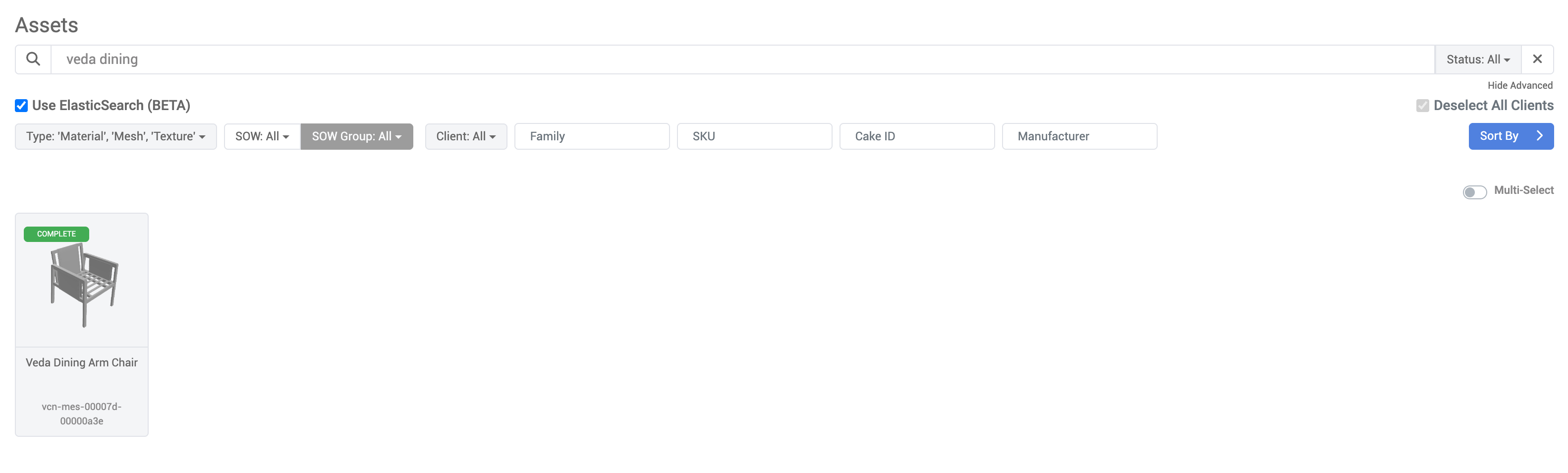
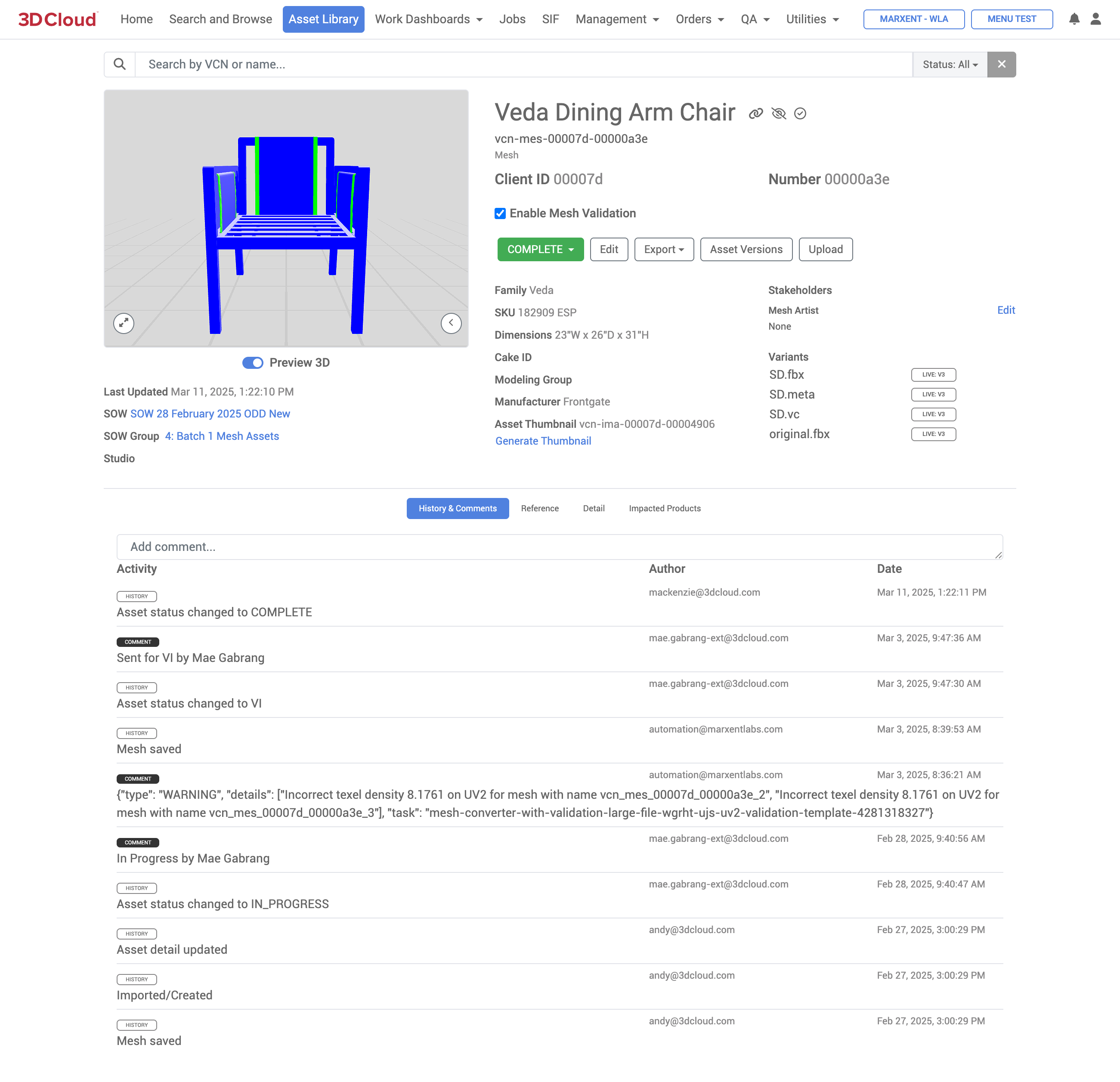
Each Asset card can be clicked to be navigated to its Asset Description Page (ADP). These pages have much more detail on an asset, and can also be used to edit details about an asset.
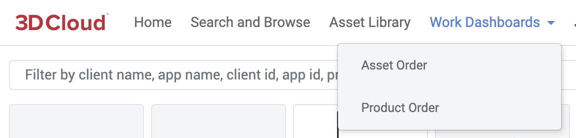
Work Dashboards
The Work Dashboards section in the 3D Cloud AMS is used by 3D Cloud associates to track the status of Asset orders and Product orders, and see the status of these items.
There are two options in the Work Dashboards navigation:
Asset Orders
Product Orders
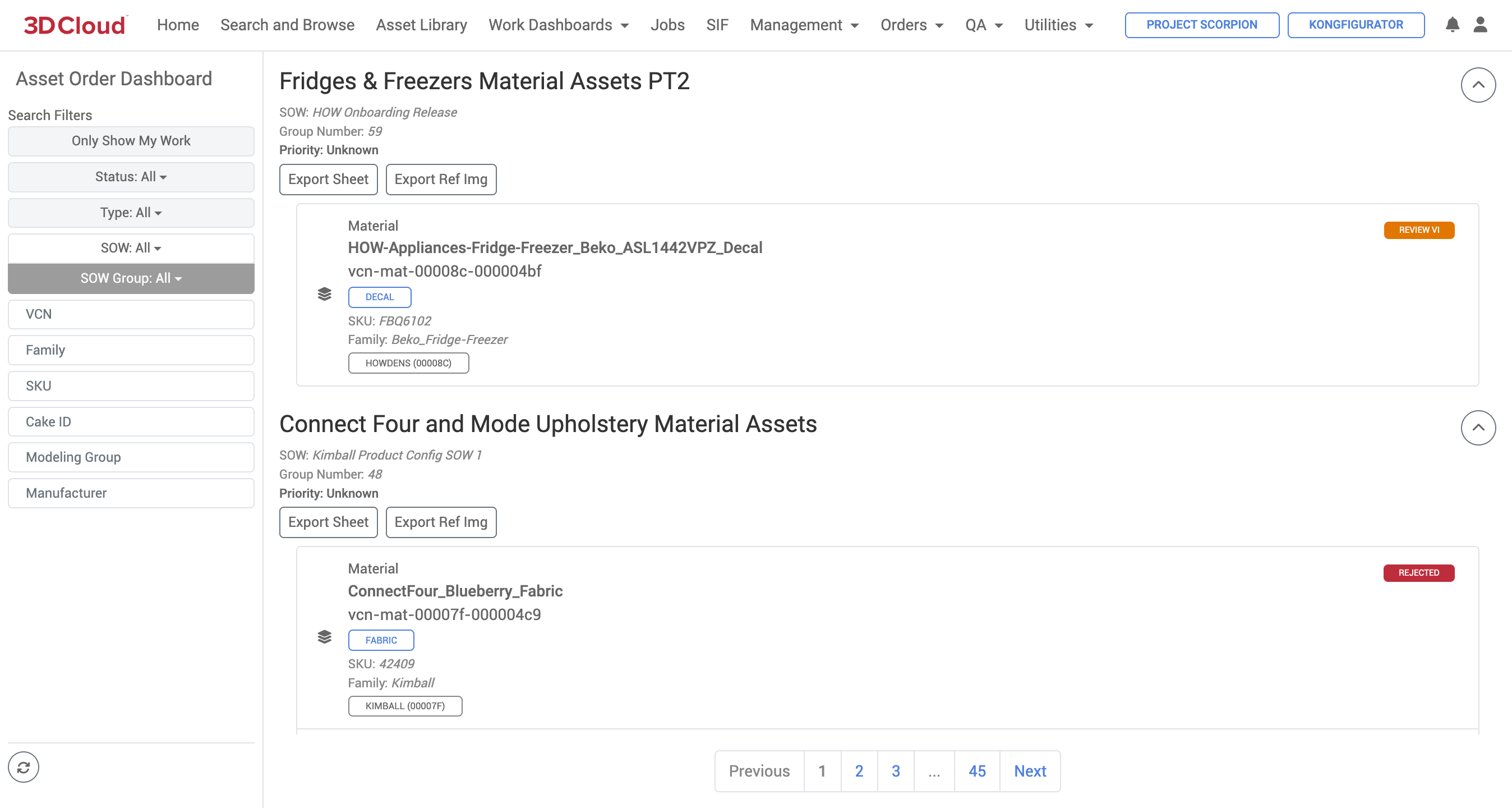
Asset Orders
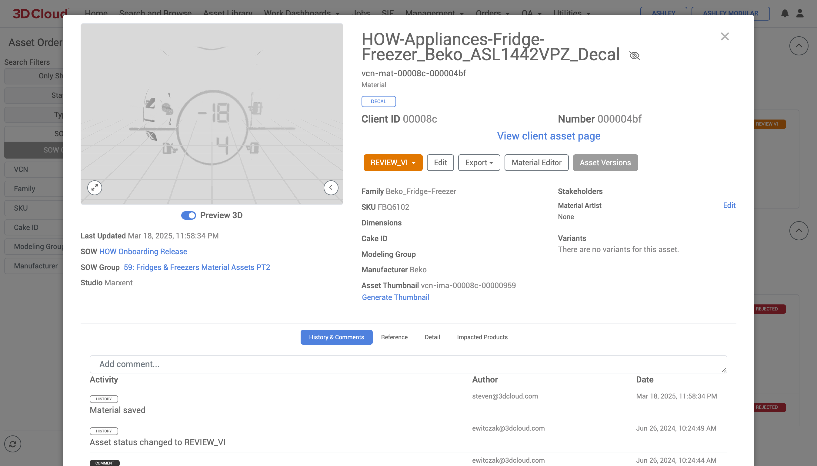
Selecting any of the entries on the Asset Orders page provide a “quick look” modal window to view the individual Asset Description Page (ADP) for that item.
Asset Description Page Modal Window
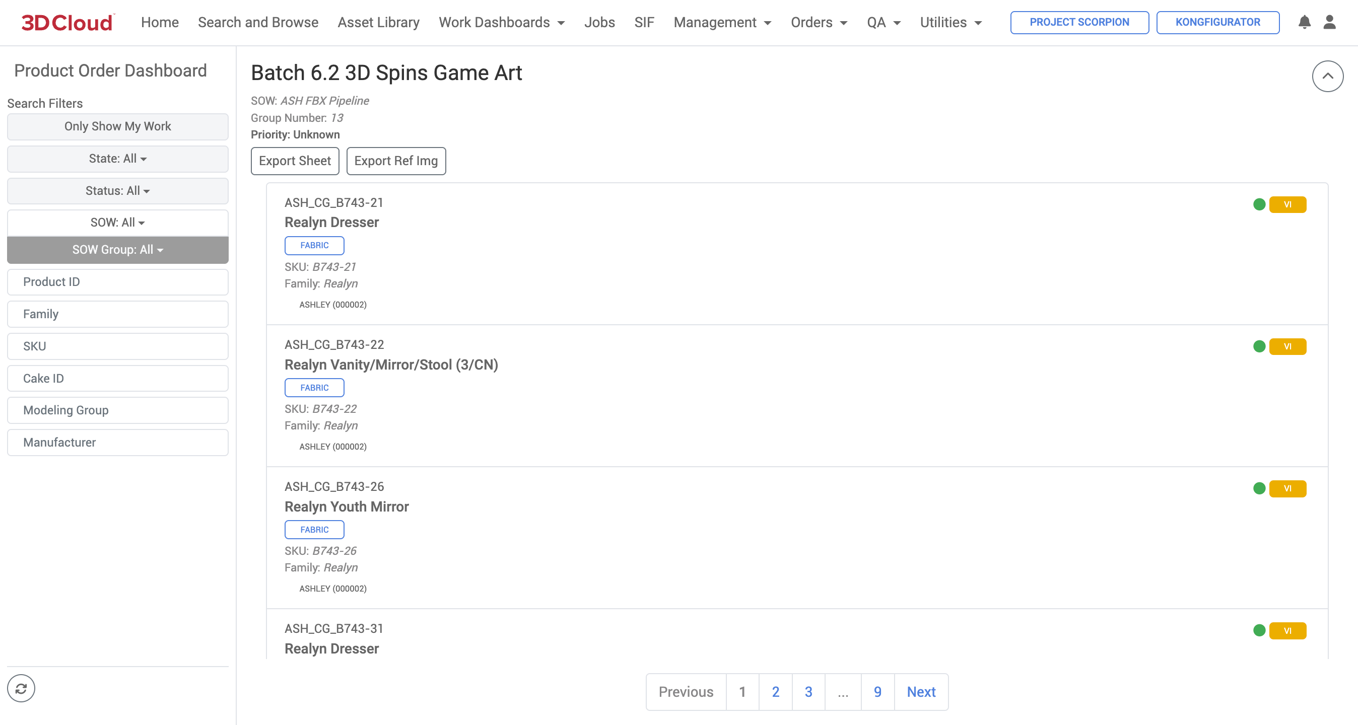
Product Orders
Selecting any of the entries on the Product Orders page provide a “quick look” modal window to view the individual Product Description Page (ADP) for that item.
Product Description Page Modal Window
Jobs
The Jobs section of the 3D Cloud AMS provides monitoring of active job submissions/executions from various sources to our Universal Job System (UJS). The Universal Job System is a highly scalable job processing framework for running catalogs, bin caches and other asset related files and tasks.
This system allows multiple jobs to run in parallel, instead of in a queue. The Jobs page is organized by and reports the status of different Job Types:
Job Type | Description (Job Examples) |
|---|---|
Client Asset | Bin Cache, Catalog, Promotion, Content Discovery Scraper jobs |
Asset Conversion | Texture conversion jobs, Thumbnail generator jobs, etc. |
Content Processing | OS Baking and Wrinkleberg jobs, USDZ conversion jobs |
Content Automated | Automated content tasks, such as processing reference image thumbnail conversions upon upload |
Product Configuration | Assembly import jobs |
Generic Configuration | Client App Setup jobs |
3D Product Configurator | Scheduled SIF jobs |
JPQL query execution | Workflow Template jobs |
All job tasks: Bin Cache generation, Catalog generation, Catalog/Bin Cache Promotion is now all on a Universal Job System.
Note: When you run a job, 3DC will take you the to “Jobs” tab.
Queued Jobs will show here with an estimated time and status
Any job that is queued that you have access to will be visible here, even if others run the job
You can filter on jobs that are Running, Pending, Succeeded, Failed, or Error. The default filter is Pending and Running.
Job action items
Setting icon: shows parameters for the job - client id, app, user, reason, and for promotions shows which environment the asset was promoted to (Stage or Active)
Envelope: events associated with the job, log failures that occurred
Stop: Temporarily stop a job
Cancel: Cancel a requested job
On Completed jobs: green check for successful jobs, red “!” for Failed jobs
Create job button. Start any job from there from the client you are under.
Management
The Management section in the 3D Cloud AMS is accessible to users via special permissions, and contains various tools to manage products, assemblies, data, orders, materials and other attributes for visualization.
Section/Tool | Description |
|---|---|
3D Product Manager | The 3D Product Manager is a command center where users can assemble a virtual product. |
Assembly Editor | The Assembly Editor allows for the management of product assemblies (e.g. a sectional, group of cabinet components, dining table/chair sets, etc.), both in their associated metadata and in 3D space where the products “attach” to each other in a specific way. |
Client Branding | Client Branding provides a generic bucket to store assets used in client app implementations. Assets might include client logos, specific icons, lifestyle images, etc. to be used in Client Apps. |
Data Manager | The Data Manager is where you can make bulk updates to your data (products, categories, and menus) through Excel-based data sheets. Data Manager can also be used to subscribe products from one client to another. |
Material Editor | The Material Editor is designed to provide a comprehensive toolset for managing and editing materials for use in 3D visualization. |
Procedural Cabinet Manager | The Procedural Cabinet Manager is a tool to create 3D cabinets using a procedural method to enhance performance and feature support. |
Product Builder | The Product Builder is an evolution of 3D Product Manager. It is where users can assign meshes and materials to virtual products and manage the swapping of textures. |
Product Template Toolset | The Product Template Toolset (formerly called “The Bakery”) is used to manage Product Templates (formerly called “recipes”) that allow users to specify a list of rules for different product category types/patterns that can be used to validate and populate product data. |
Snappy | Snappy is a tool used to set how a configuration of product components should “snap” together in 3D configurator apps. The tool provides live 3D, real-time fine-tuning of component positioning and snap points. Examples include sectional components, configurable arm components, etc. |
Spec | The Spec section manages the highest level of definition of what data a product needs. When a product is being activated, or validated to see if it is complete, or has regressed, we validate it against the entire Spec. Specs can be generic across all clients or specified down to a specific client. A spec that is built for a specific client can be generalized across clients in the future if needed. |
Stores | The Stores section manages the creation and repository of client-specific Store IDs. Store IDs may be used in apps like the Room Planner to allow customers to select a specific store to enable usage tracking and Client App KPIs per store. |
Typed Attributes | The Typed Attributes section manages client-specific data attributes associated with products or virtual products, often used in various configurations and settings. They are defined with specific keys and values that dictate how a product behaves or is displayed in a system. |
User Productivity Dashboard | The User Productivity Dashboard reports on the number of products and assets created through the 3D Cloud AMS by 3DC user and date range. For 3D Cloud associate use only. |
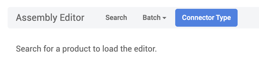
Assembly Editor
The 3D Cloud AMS Assembly Editor allows for the management of the arrangement of multiple products (called “assemblies”). The tool helps specify the underlying association of how the products fit or snap together, using metadata and 3D space coordinates. Wtih the tool you can:
Take 3D models (meshes) that have been assigned to PIDs (Product IDs) and add functional data and behavior to them
Enables products to have interactive features like material swapping, sectional sofa-type connectivity, and composable surfaces
Common applications for assemblies include sectional furniture or complex assemblies with multiple connection points. Currently, the Assembly Editor provides a number of benefits, including:
Speed and Efficiency in Authoring
Bulk Operations: Can process hundreds or thousands of products at once using spreadsheet imports
Template Replication: Once you have a working template (like a simple cover step), you can replicate it across many products quickly (e.g. large furniture collections with similar functionality)
Batch Processing: The Step Generator allows bulk updates across multiple PIDs simultaneously
Simplicity for Basic Products
Straightforward Setup: For simple products with just material swaps, assemblies are much faster than building full configurators
Less Overhead: No need for complex configurator logic when you just need basic functionality
Loading a Product
In 3DC under Management → Assembly Editor, search for an existing product using the Search button on the top navigation toolbar.
If this product does not yet have an assembly, you can create a new one by clicking the Load → Create New Wizard button. You will be prompted to provide a name for this wizard:
Note: The Category Tree Editor is contextual to the currently selected Client App.
Adding Steps
Steps are the building blocks of assemblies. There are different “step types” that may be used, which trigger specific functionality in client applications. Common types of steps include:
Empty Step: A basic step that can be customized as needed.
Preset Steps: These are pre-configured steps for common use cases, such as:
Lamp Step: Used for adding a lamp composable surface position
Table Step: Used for creating tabletop composable surface bounds
Material Swap Step: A step specifically for swapping materials on the parent product mesh
Step Groups: Steps can be grouped together to allow mutually exclusive choices in the UI
Mount Point Steps: Steps that define mount points for positioning components in 3D space
Composable Surface Steps: Steps that define surfaces where other objects can be placed, such as a tabletop or lamp base
To add a new step, click the Add Step → Empty Step button on the top navigation toolbar. The 3D Cloud AMS also provides the ability to add step presets, like Lamp and Table.
Deleting Steps
To delete an existing step, click the Delete Step button on the bottom of the step card.
Re-ordering Steps
Assembly wizard steps can be re-ordered by dragging their cards within the step list.
Note: All steps with a Step Group will be assigned the same order number.
3D Editor
Mount Points
Mount points are specific coordinate positions on products that define where and how objects can connect to each other. Without mount points, assemblies like sectional furniture would just be individual pieces with no way to connect. Mount points enable the creation of complex sectional furniture systems where customers can build custom configurations that automatically “snap” together properly.
Key Facts about Mount Points
They have precise 3D coordinates (X, Y, Z positions) on a product where connections can occur
They can include rotation values (like -90 degrees on Y axis for corner sectional pieces)
Include both position data and connector logic that determines compatibility
Enable sectional furniture pieces to "snap" together properly through preset connector logic (like "sectional middle left" or "sectional middle right") anc compatibility rules (e.g., "Middle Left" connects to "Corner Rights, Middle Lefts, and LAFs")
Show up as dots in the interface (Default is blue, but urn pink when a compatible connection is detected nearby)
Can be toggled on/off for visibility during setup
After adding a step, we can start to manage this assembly in 3D. On the bottom right-hand pane, click the Add button to create a new point point for the currently-selected step. The order of mount points in this list determines the order written to the database. Use the arrow keys below the list to reorder points.
Mount point positioning can be modified by changing the form fields under the 3D editor, or by dragging the mount point directly in the scene. Additionally, the arrow handles can be used to move the point along a particular axis.
Compose Surfaces
Composable surfaces are invisible 3D planes or areas that define where objects can be virtually placed on top of other objects. Here’s how they work:
They create a defined area (like a rectangle or plane) on a product where other items can be positioned
The surface itself is completely invisible to users - it's just functional logic
Objects with compatible connectors can be placed anywhere within the boundaries of that surface
Examples of Composable Surfaces
Pillows on sofas: A composable surface on the sofa seat allows pillows to be placed anywhere on that surface
Lamps on tables: A table has a composable surface on its top that accepts lamps or decorative items
Accessories on shelves: Each shelf in a bookshelf needs its own composable surface for placing decorative items
These surfaces can be managed by clicking the Compose Surfaces button above the mount point list.
Note: that this compose surface is associated with the currently-selected mount point.
After adding a surface, its bounds can be modified via the form fields, or by dragging the handles on its corners in the 3D scene.
Other Controls
View Mode
The 3D view mode can be toggled with the view buttons on the bottom of the Assembly Editor. To view the assembly context while in full-screen 3D mode, click the menu icon in the bottom left-hand corner.
Connections
Mount point connections (on Ordered Mount Point steps) can be toggled by clicking the Hide Connections button in the bottom right-hand options menu in the 3D scene.
Compatible Products
In addition to selecting a product for the current step via the Selected Product input, we can temporarily swap compatible products into the scene via the MACs tab in the step list.
Search for a MAC to make compatible for this assembly wizard step, then click the Menu icon in the resulting list to load a browser of all compatible products. Click on the product thumbnail to load it into the scene.
Note: This selection will not be persisted.
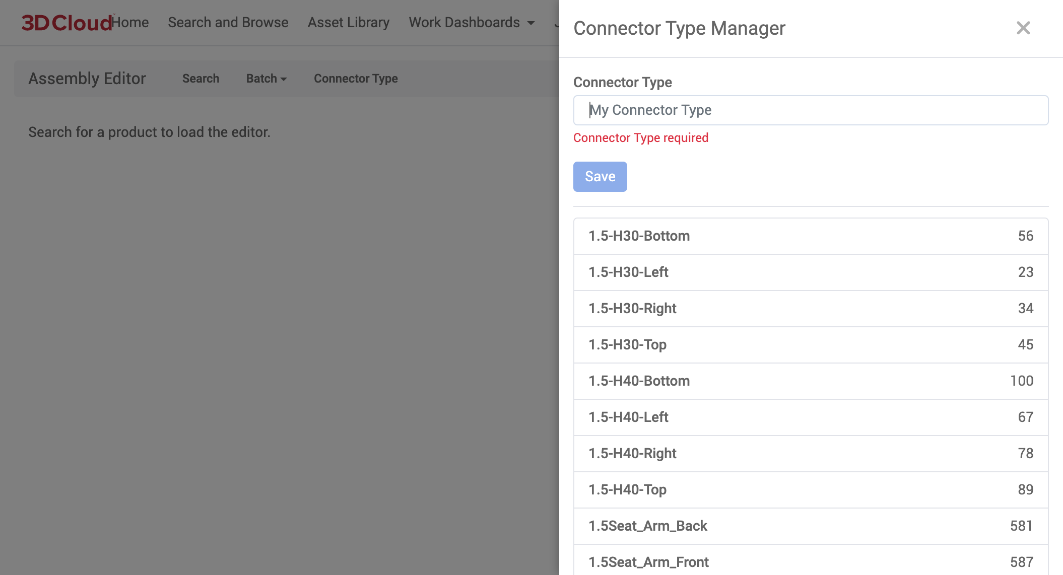
Connector Types
Connector types are primarily used in assemblies. They are universal so newly defined connector types should be used sparingly.
Permissions
Assembly.Read
Assembly.Create
Manage Connector Types
Go to Assembly Editor → Connector Type
After selecting the Connector Type button, the management utility will slide out from the right.
To create a new connector type:
Enter the name of the connector type and hit the Save button
A list of existing connector types is displayed below the create functionality.
Client Branding
Client Branding provides a generic bucket to store assets used in client app implementations.
Viewing Branding Assets
To view a collection of branding assets, navigate to Management → Client Branding. Click on the individual asset card to view the full image.
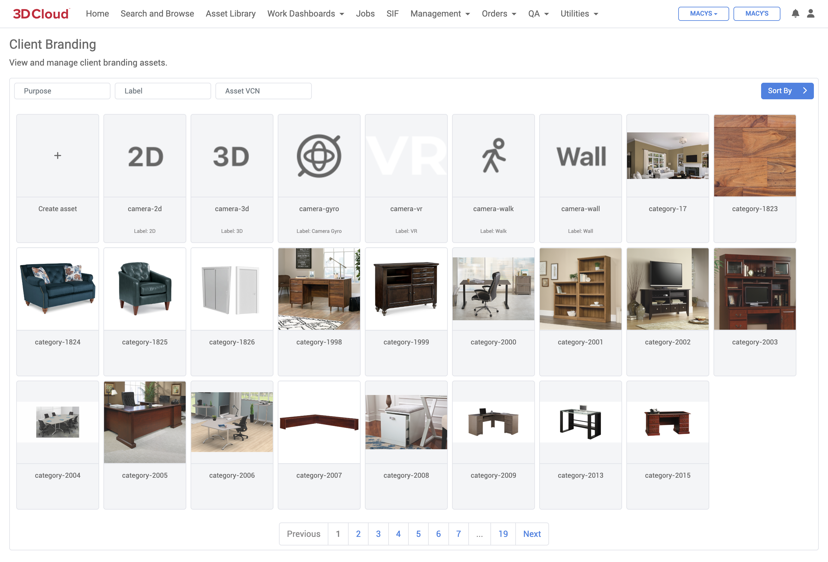
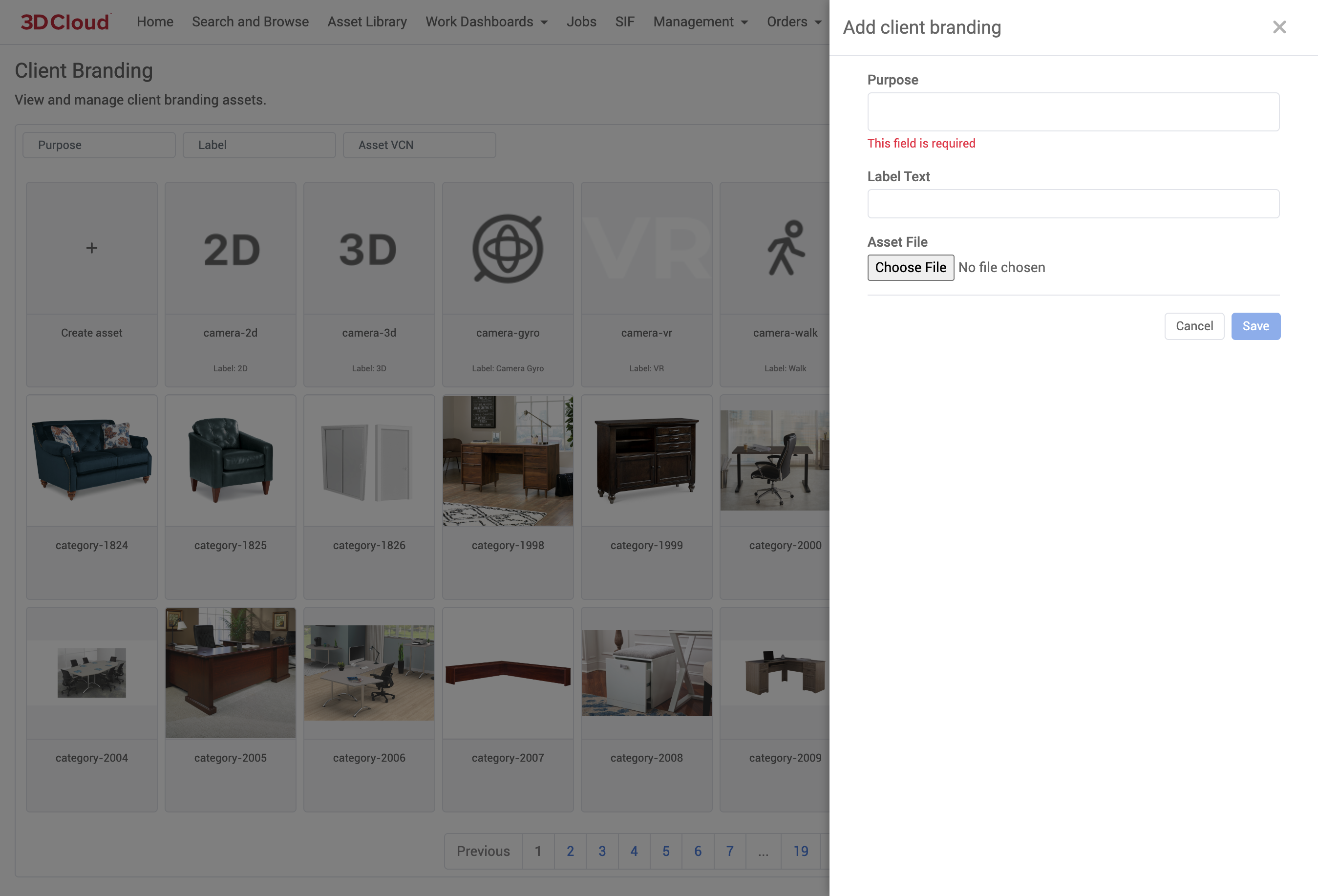
Adding Branding Assets
To add a new branding asset, click on the Create Asset card on the top-left of the asset browser. Enter a purpose for the asset (note that it must be unique for the current client) as well as an image file. On save, the image will be sent to the job server and will be associated with a new branding record.
Editing an Existing Branding Asset
To edit an existing branding asset, click on the Edit “wrench” icon that appears in the top-right corner when hovering over an asset card. Here, you can change the associated image of the branding record. To delete the record altogether, click the Delete button at the bottom of the dialog.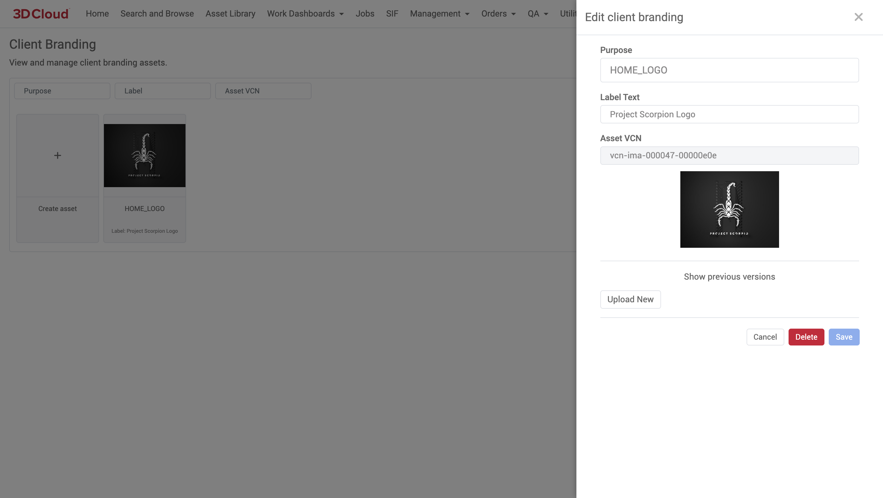
Data Manager
With Data Manager, you can make bulk updates to your data (products, categories, and menus) while maintaining a history of changes made to those entities. Since Data Manager validates these updates against a spec, you can more confident that data changes won’t negatively impact your applications.
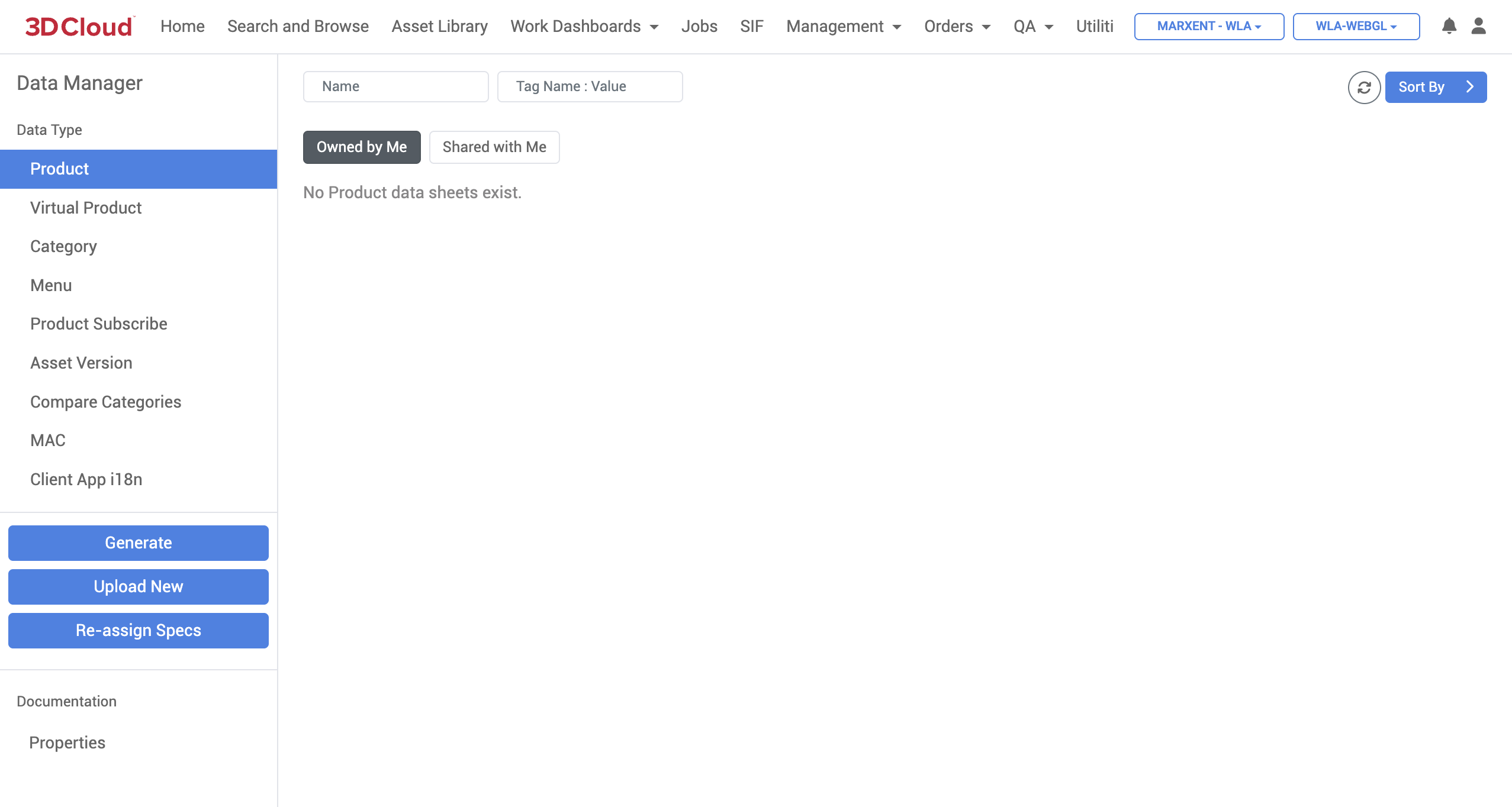
Generating a New Product Data Sheet
Generating a data sheet will create a spreadsheet file with all the appropriate column data pre-populated, using a selected group of products.
Begin by selecting the Product Data Type, under Management → Data Manager. Click the Generate button to get started.
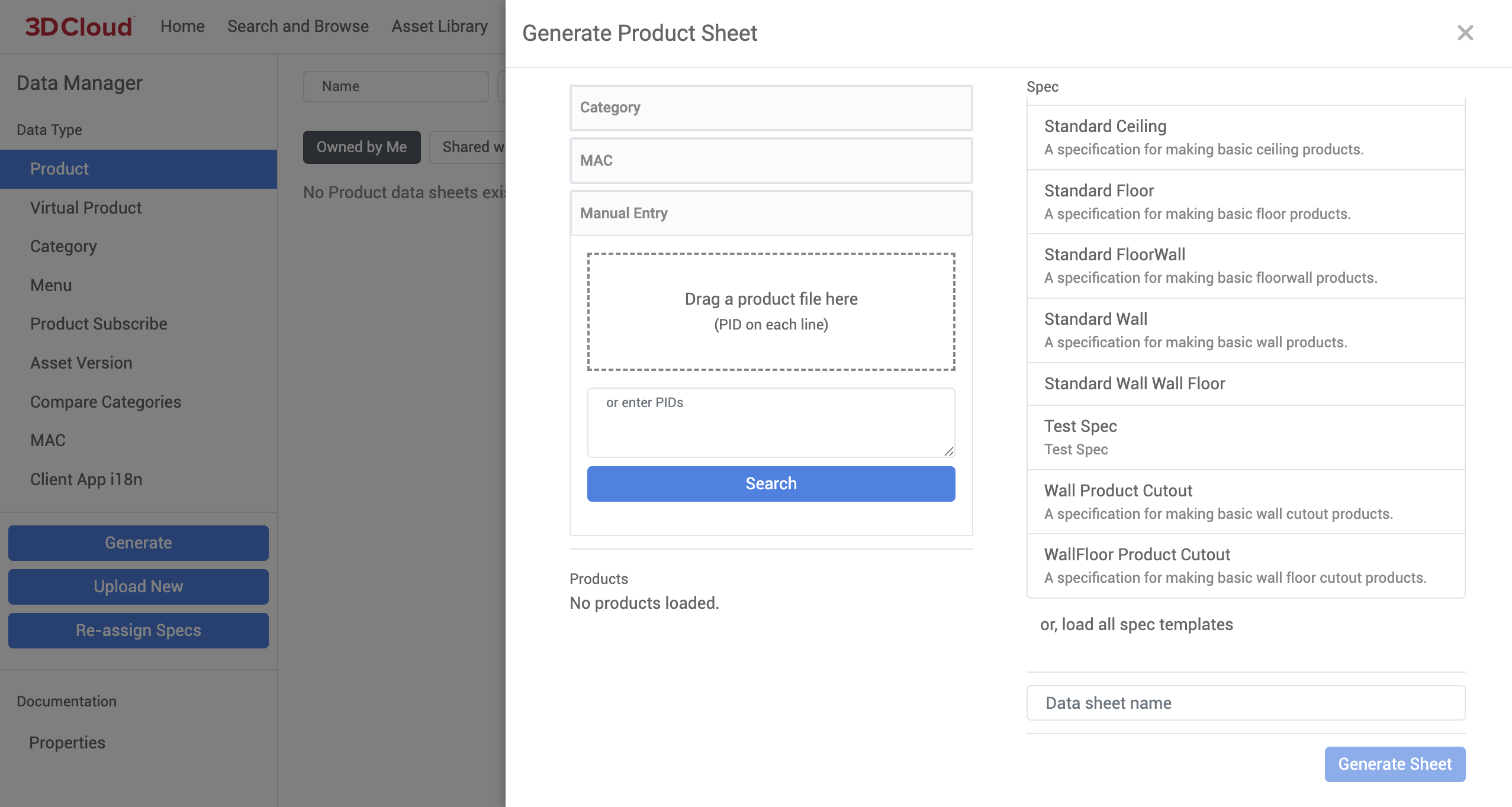
Select a source from which to load product IDs. You can load products from a particular category, by SOW Group, or by MAC. For now, we’ll just use manual entry.
Once you’ve selected the products you wish to update, choose a spec template to validate this data against. This will also determine the auto-generated columns in the newly-generated data sheet. Give the data sheet a name, and click Generate Sheet to save and download this new sheet.
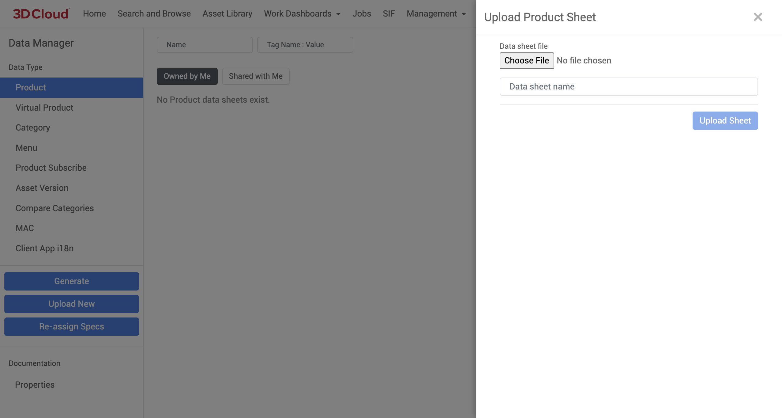
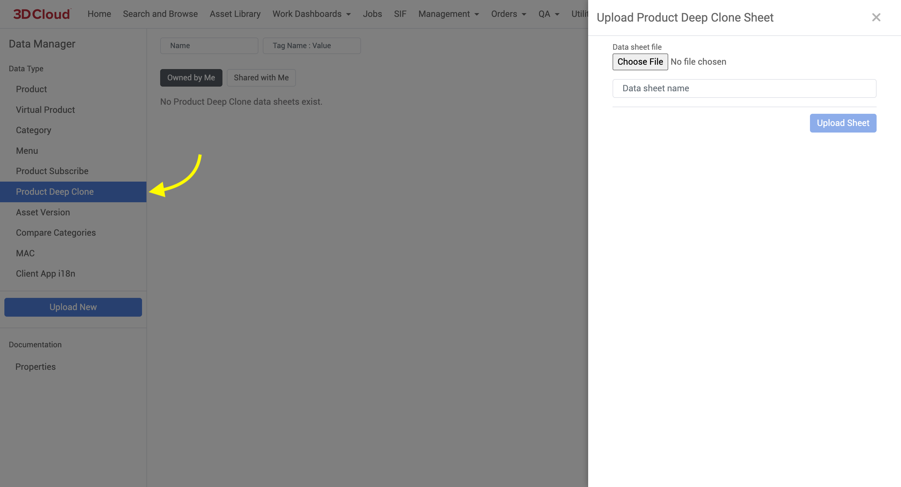
Uploading a New Data Sheet
Data Manager also provides the ability to upload a manual data sheet without having to generate from a data spec or from product IDs. Under the Data Type heading, press the button. From here, choose the location of the data sheet file you wish to upload, give it a name, then click Upload Sheet to create a new sheet entry. Note that this will begin a new revision history of data sheet files, and should not be used to upload a new version of an existing sheet.
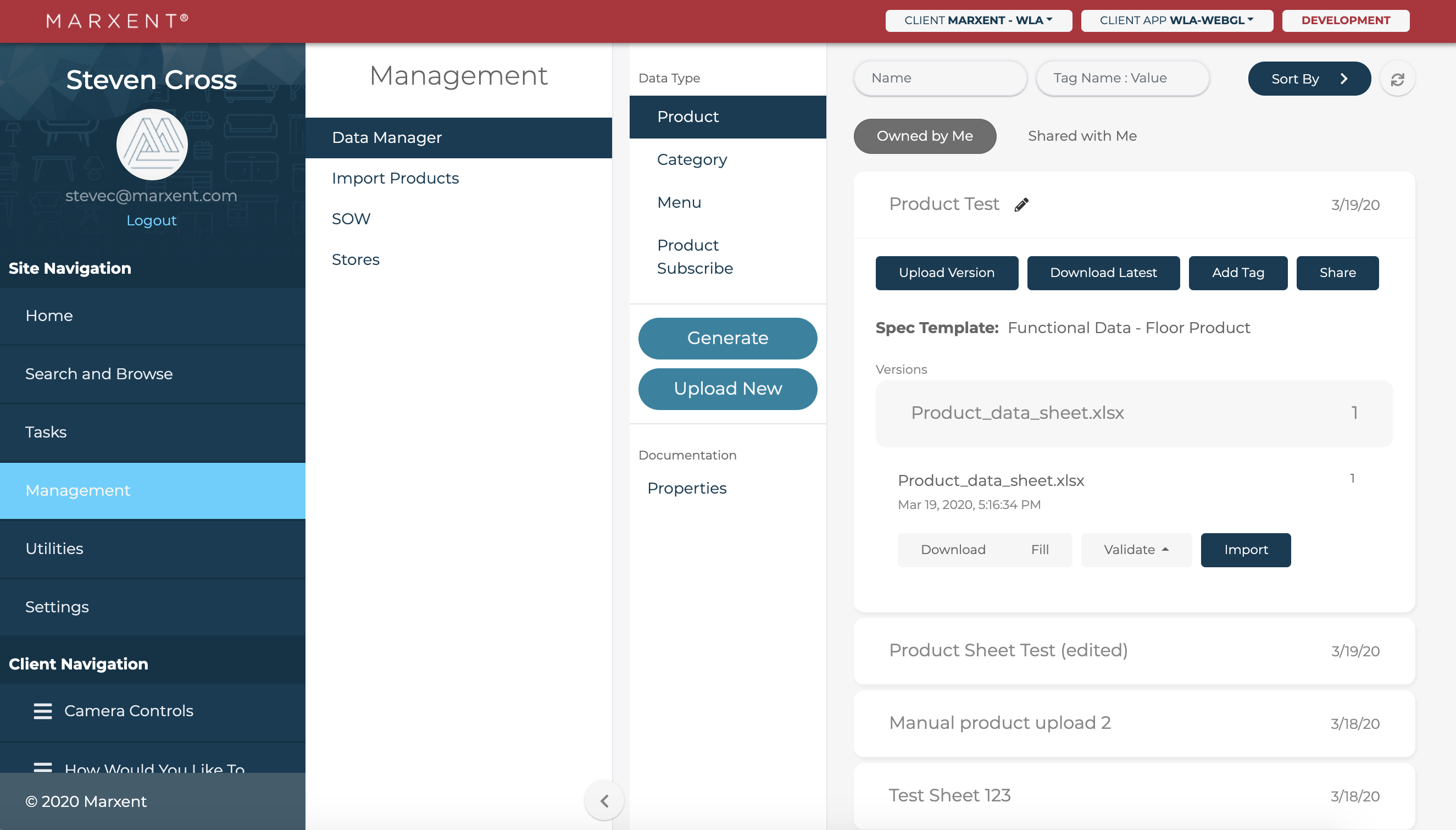
Managing Existing Data Sheets
Now that we’ve generated/uploaded a data sheet, we can validate and import the data inside, or even manage the different versions of the sheet.
On the right-hand side of the Data Manager window, you’ll see a list of data sheets which have been uploaded into the system. Expand one of these entries to see the versions of the sheet, as well as other management actions.
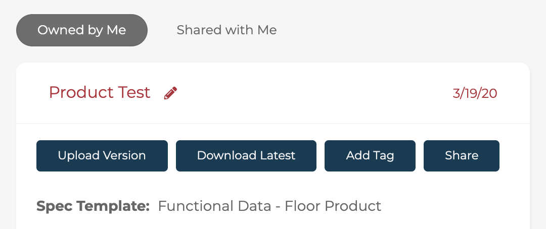
Data Sheet Actions
Upload Version: Uploads a new version of the selected data sheet. This allows us to keep a history of changes made to a particular set of entities.
Download Latest: Downloads the latest version of this data sheet file.
Add Tag: Tags a data sheet for easier searching.
Share: Shares this data sheet with another user (by username), allowing them to manage the data.
To edit the name of a data sheet, click the edit icon beside the existing data sheet name.
Version Actions
Click on the version filename to reveal actions which can be taken for this particular data sheet revision.
Download: Downloads this version of the data sheet file.
Fill: Fills this data sheet version with any existing data in the database.
Validate: Validates this version against a data spec or spec template.
Import: Imports this data sheet version into the database. Note that this action cannot be undone, unless a previous version is used to revert changes.
Product Subscribe
The Product Subscribe tool may be used to take a product from one client, and move everything 3D-related about it (mesh, material, assembly information) to another product as a “shared” asset.
The product data (e.g. SKUs, URL, Category, Product name, etc.) will be net new for the new product that is being created and can be changed without affecting the original product data from which it was subscribed.
Common use cases for this feature include:
Making individual subscribed product(s)
Setting up a new client with templated set of standard products, materials (e.g. paint colors for a new room planner client) that share common 3D assets but need new names or metadata.
Training Video
Basic Subscribe
This training video walks through the process of subscribing products from one client to another (older interface shown, but functionality remains the same for the latest version of the 3D Cloud AMS).
New App/Client Subscribe
Step-by-Step Instructions
Make sure categories in the new client are already created to match with original categories. You can copy a category tree from 3D Clcloud and create that same tree in the new client using the data tools
To subscribe one or more product(s), navigate to Management → Data Manager→ Product Subscribe (left menu).
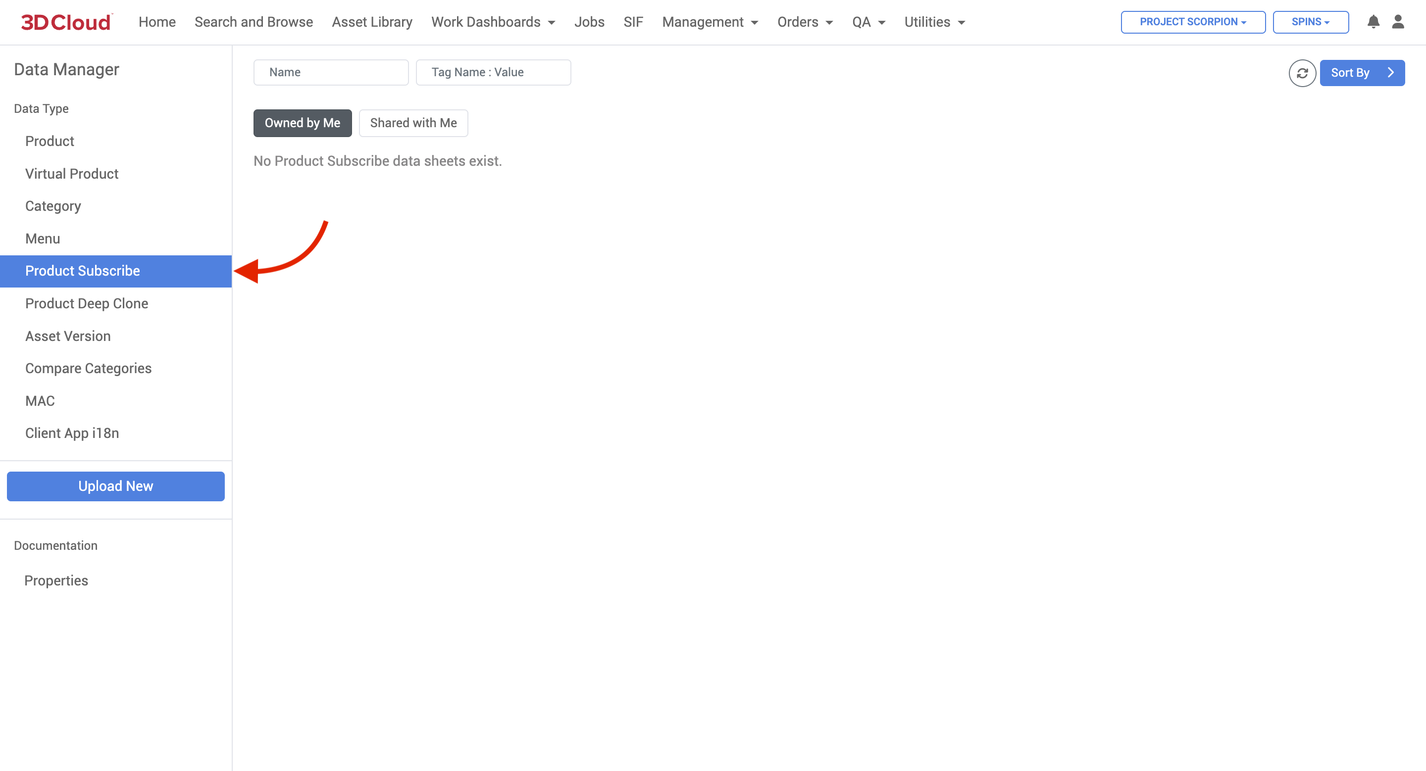
Data Manager can be used to bulk subscribe products from one client to another. Click the Upload New button. The data sheet must have two columns, “Original Product” and “New Product“, where the Original is the product ID to copy from, and the New is the product ID to copy to. Also, ensure the sheet name is “Data”.
Other Documentation
Documentation on data specs as well as data sheet formatting can be found under the Documentation → Properties link.
Product Deep Clone
The 3D Cloud AMS Product Deep Clone tool allows the user to create a “clone” or duplicate of a product ID from one Client to another (or within the same Client), including all related assets (images, meshes, materials, textures), assembly steps, and functional data that will be no longer linked in any way to the source product from which it is cloned.
The ability to employ the Deep Clone feature to save time in setting up functional data to create new products similar to previous ones is a key benefit. Having the cloned product separated from the original means that changes can be made to functional data, meshes or material settings without any dependencies.
The Product Deep Clone feature is accessible at Management → Data Management → Product Deep Clone
How to Create a Product Deep Clone
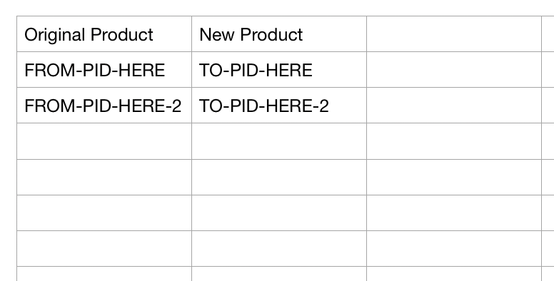
To create a deep clone, first fill out an .xlsx data sheet set up as shown below, you can clone one or many Original Products which are entered one per row.
.png)
The original Product ID is in the first column.
The new Product information is entered in the second columns…and on.
Any of the standard product properties can be specified in the sheet, should you want to change the data.
The “New Product” (second column) should have the proper Product ID for the desired cloned product.
The “Clone Assets” (third column) is set to TRUE if you want to clone all the related assets (meshes, materials, assembly steps, etc.)Navigate to the Client that you want the cloned Product ID to reside.
Click the Upload New button and use the “Choose file” button to select your .xlsx data sheet and provide a name for the job.
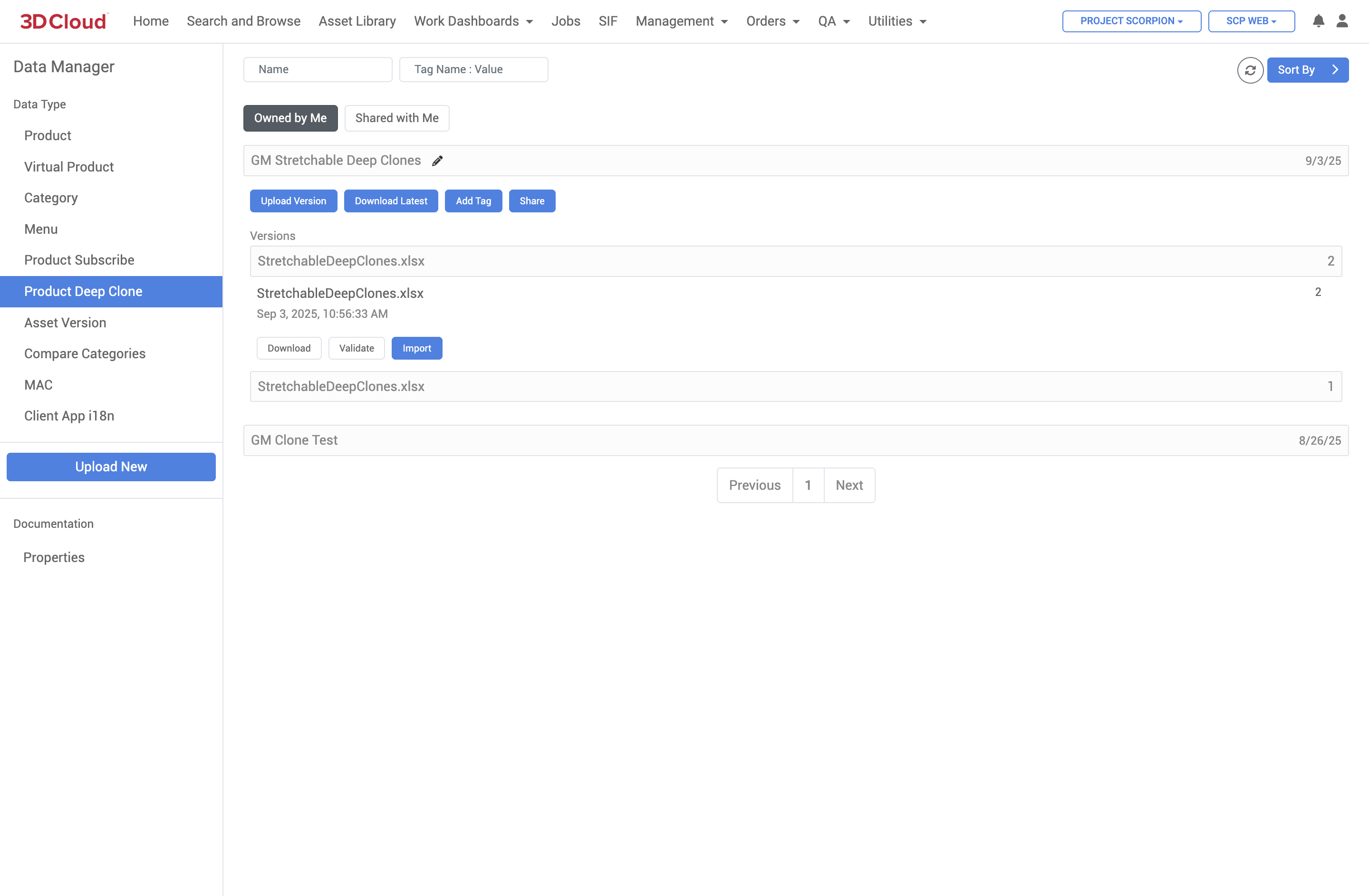
Open the drawer for the Deep Clone job you just created, you will be able to upload versions of the xlsx files. Click on the xlsx file version you uploaded and click the “Validate” button. You should see a confirmation message saying that the sheet is valid.
You may get validation exception errors if:Your source Product IDs do not exist
Your destination Product IDs already exist
You are trying to clone but are not on the right Client (Product IDs should have the 3-letter prefix of the Client you want to clone to)
.png)
.png)
After successfully validating your sheet, click the “Import” button. Leave the browser window open until the job is complete. You can monitor the job status in a new tab, in the Jobs → Client Asset tab.
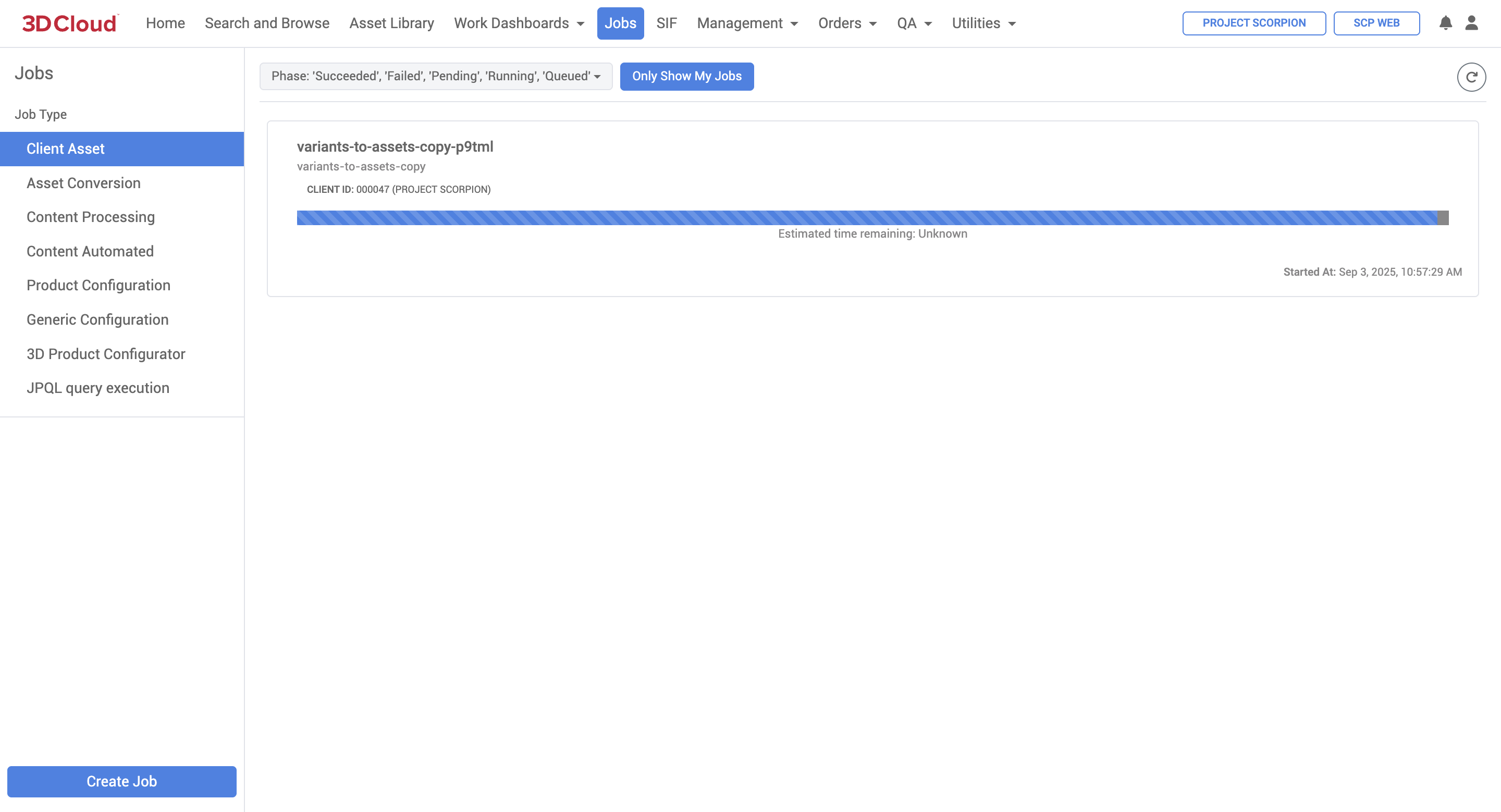
Deep Clone Job Status (Running)
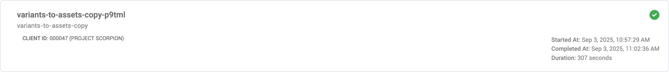
Deep Clone Job Status (Complete)
The cloned product(s) will be created. Verify the creation in the new Client Search and Browse.
Material Editor (2.0)
The Material Editor is designed to provide a comprehensive toolset for managing and editing materials for use in 3D visualization.
To access the Material Editor in the 3D Cloud AMS, a special feature called Material Editor (3DC) is required on the 3DC user account. This feature is bundled with other roles in 3DC, such as the Default 3D role.
Users have the option to Create, Search or Load materials from a SOW Group or by entering VCNs manually.
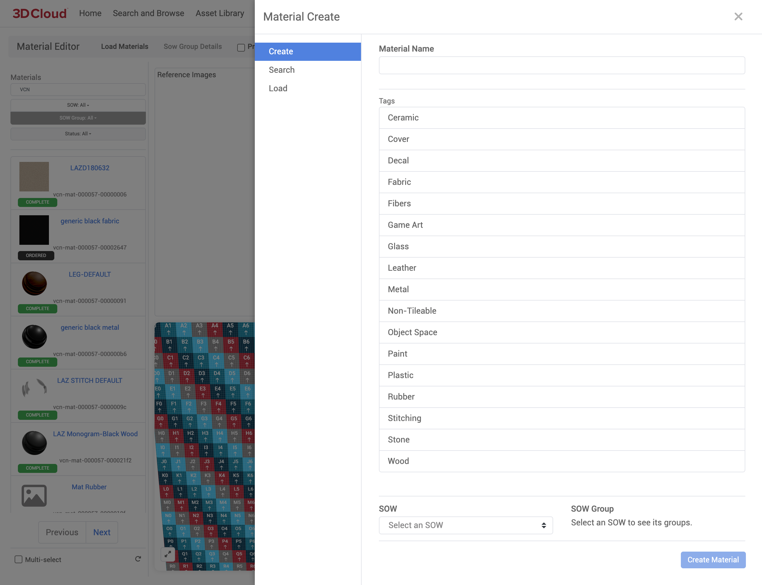
Create Material
Create Material generates a brand new material vcn with your desired Material Name. 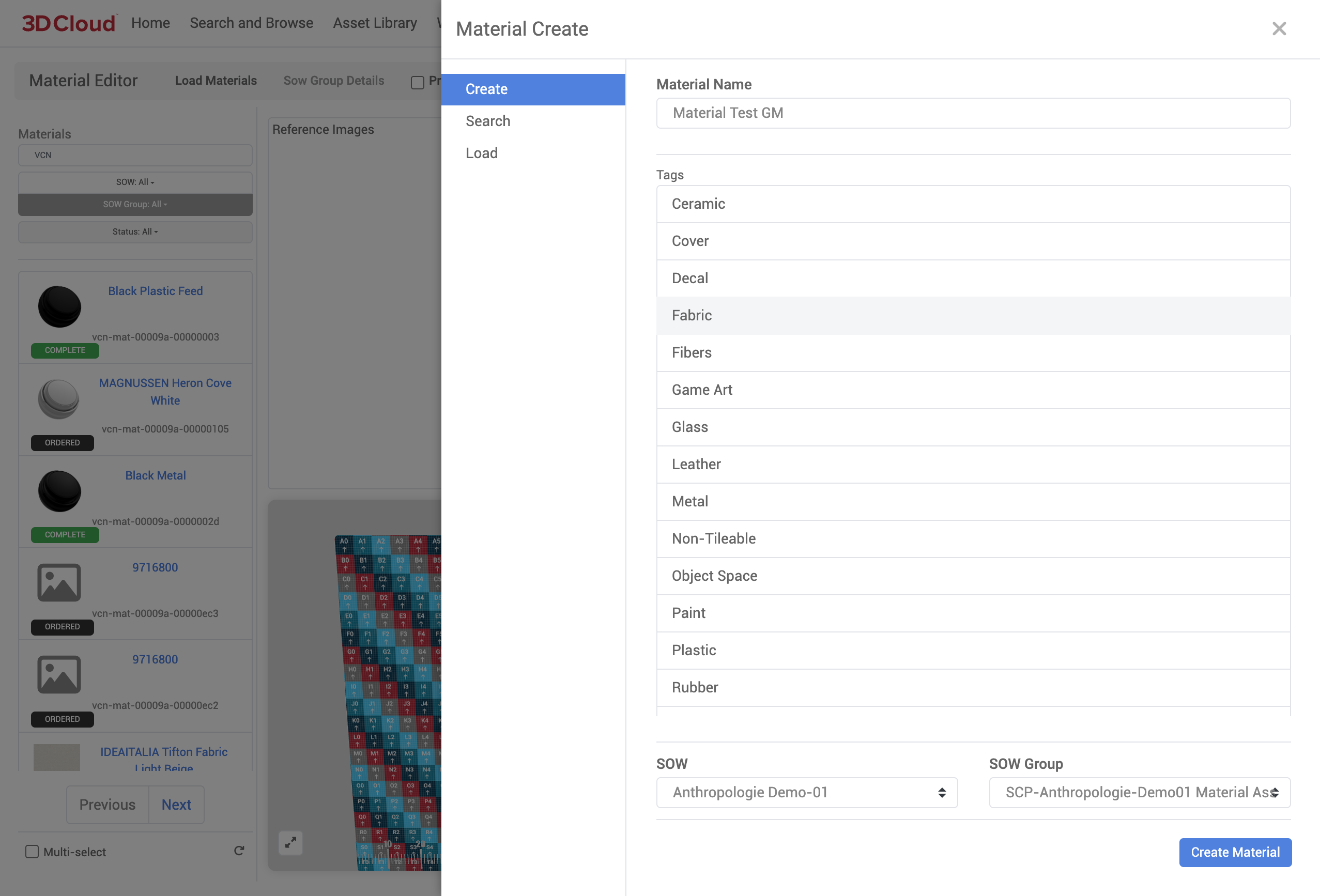
Materials must have a specific tag identifying the type of material. Options include:
Material Tags
Ceramic
Cover
Fabric
Fibers
Game Art
Glass
Leather
Metal
Non-Tileable
Object Space
Paint
Plastic
Rubber
Stitching
Stone
Wood
SOW / SOW Group
You can associate the new created material to an existing SOW or SOW Group using the dropdown menus.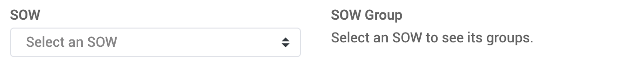
The new, blank material vcn is created, associated to the material name provided.
Loading Existing Material
Existing materials can be loaded for editing purposes. Materials (multiple materials can be loaded) can be selected from existing SOW Group or Manual Entry of Material VCN.
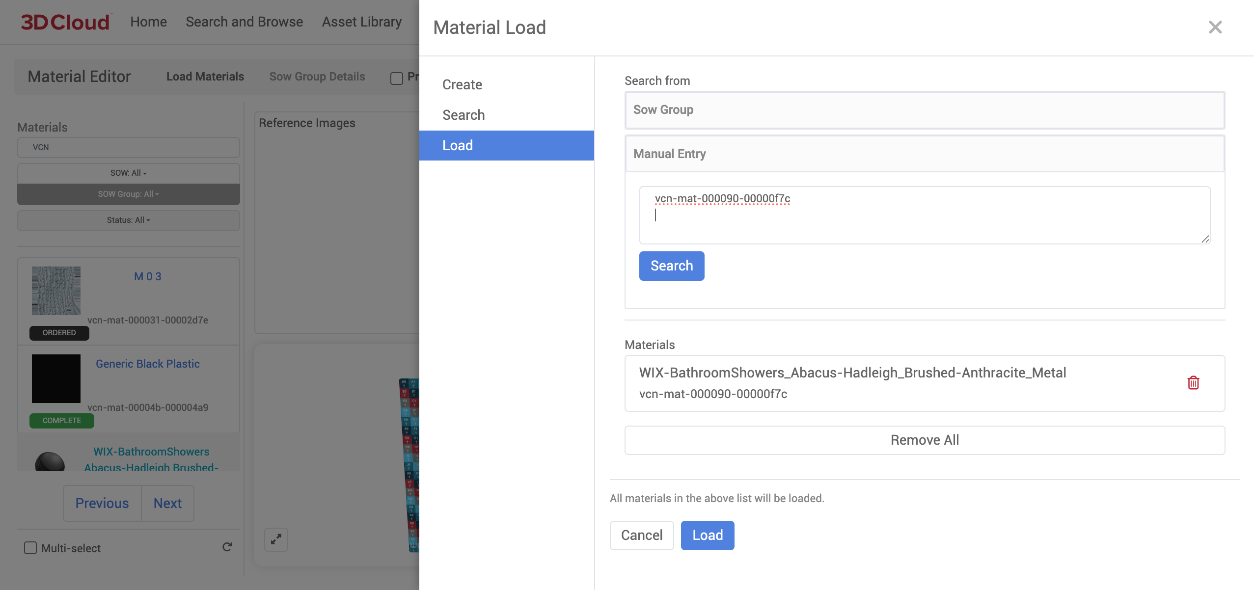
When loading Material Editor for the first time, the menu on the left will be populated with default material vcn’s from all SOW Groups and All Statuses.
Note: SOW Group - SOW Groups must be LOCKED or they will not show up in the dropdown filter.
Material Reference Images
Now that you’ve Selected a Material, the Material Description Page is displayed.
The first thing you’ll notice is the Reference Images WebGL renderer viewport in the top left.
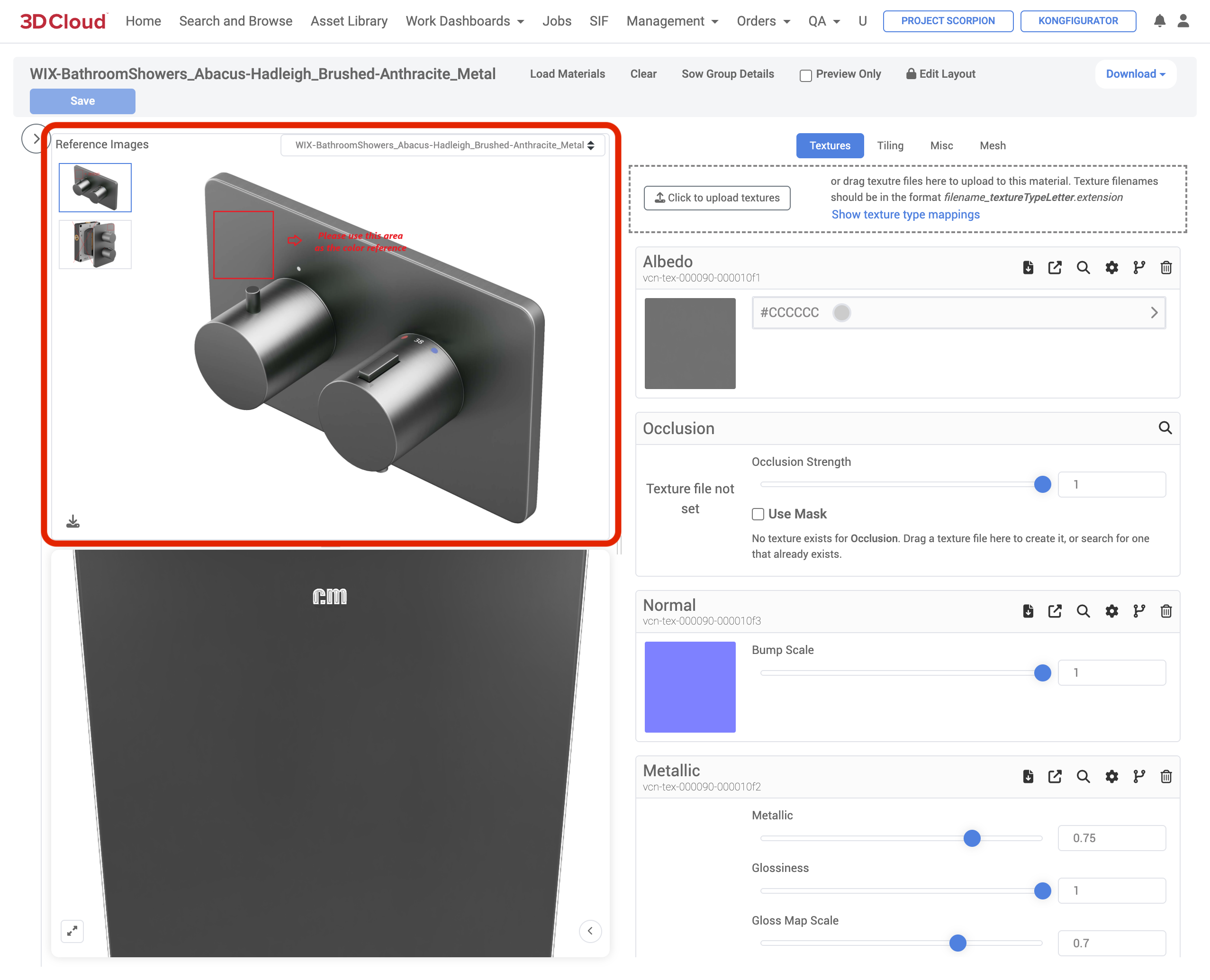
This convenient window stores the Reference Images for the Material Asset, allowing users to do advanced actions:
Select specific Reference Images
Select specific Shared Reference Images between subscribed Products
Zoom in/out
Download the Reference Image
View the Name of the Reference Image
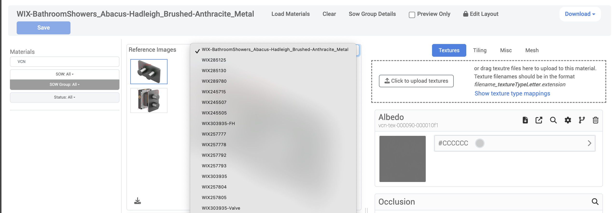
Shared Reference Images
If the Material is shared with other Products, an additional dropdown menu will appear, allowing you to view the Reference Images on each respective Product:
3D Viewport
On the Material Description Page on the bottom left is a 3D WebGL renderer viewport with the ability to maximize the view, edit the layour to rearrange the Reference Image, 3D Viewport and Texture panels, and access options for Advanced Tools.
Textures, Tiling, Misc, and Mesh Panels
Selecting these tabs allow the user to perform a variety of actions.
Panel | Available Actions |
|---|---|
Textures | Upload textures Edit settings for Albedo, Occlusion, Normal, Metallic, and Emission, Detail Albedo, Detail Normal, and Detail Mask files:
|
Tiling |
|
Misc | View Material VCN View Tags Set Material Plugin, Render Mode, Shader, Preview Mesh Select Additional Properties:
Select Distressed
Select Khronos Textures
|
Mesh | View the currently selected mesh and it’s materials For Selected Material:
|
Download All Materials
Users now have the ability to Download all Materials or just the Material Reference Images as .zip files.
Note: Reference Files will download on a per Product basis. This means if you use Multi-Select to pick more than one VCN and then Download the Reference Files, you will receive one .zip per VCN.
.png)
Product Builder
The Product Builder section in the 3D Cloud AMS is where users can assign meshes and materials to virtual products, manage the swapping of textures for products with multiple options,
The process of product building typically happens after virtual product IDs are created and mesh assets are completed and ready to assign to the virtual product. Material assets to assign to the product may be already complete, or can be built “on the fly” in some cases by the 3D Cloud 3D artist team.
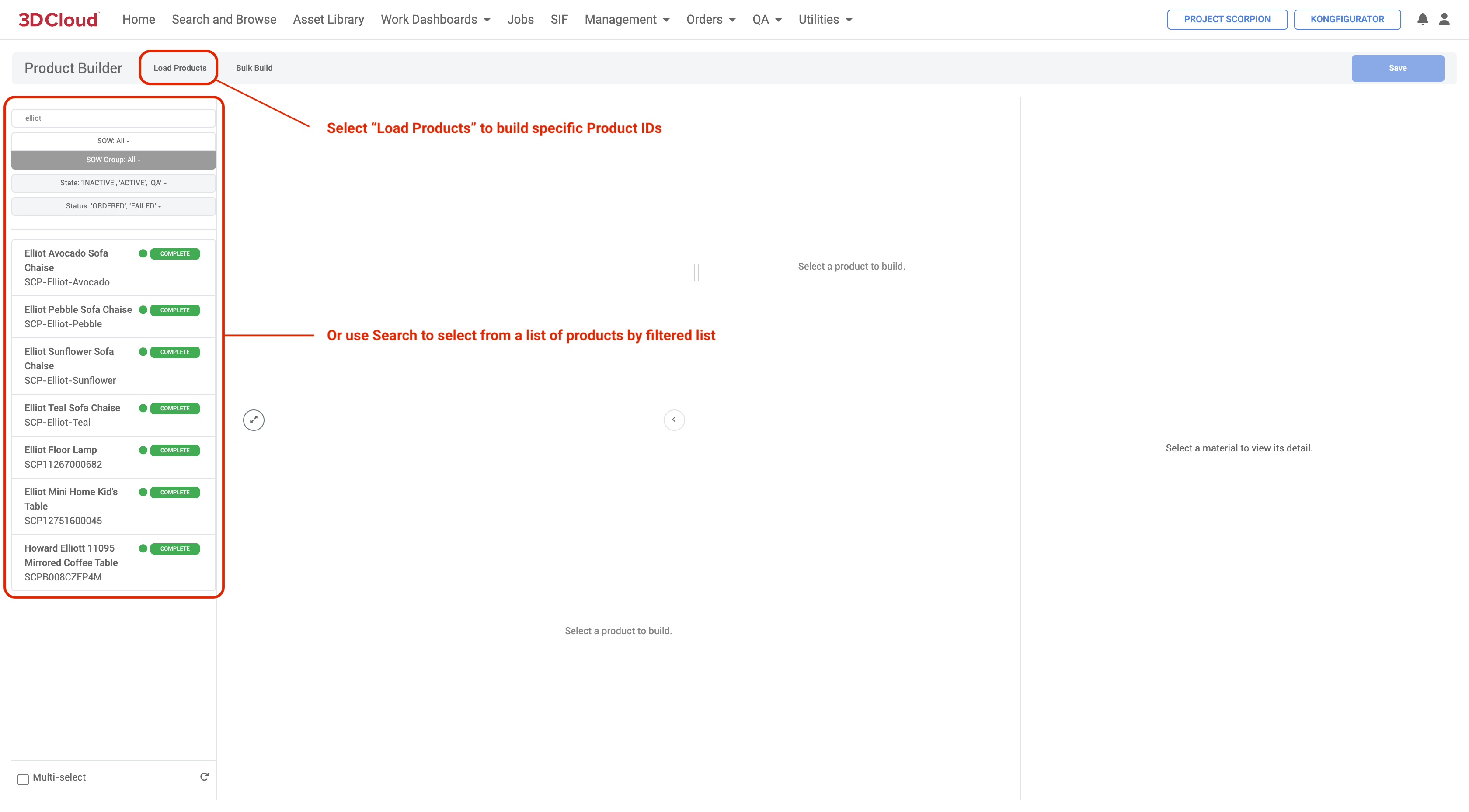
Selecting Products to Build
Users can upload new meshes or search the asset library for a mesh that has already been created.
Select a Client then navigate to Management → Product Builder.
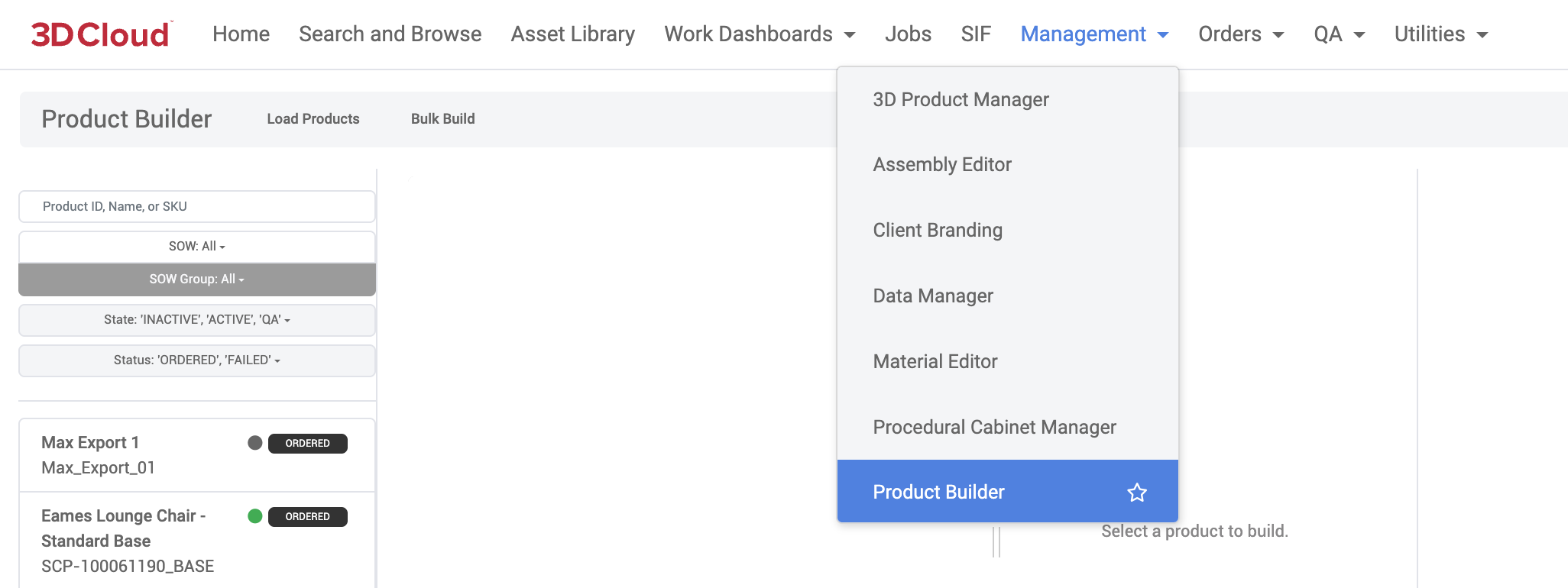
Either search for a specific product you wish to work on (by Product ID, Name or SKU) or use the filters to click on a product from the product list on the left panel that loads once the feature loads.
Swapping
In cases where a traditional assembly is used for specific products, the associated product options are shown in the WebGL preview on the product build page when you select the Swapping blue tab. These products options are configured onto the assembly using MACs.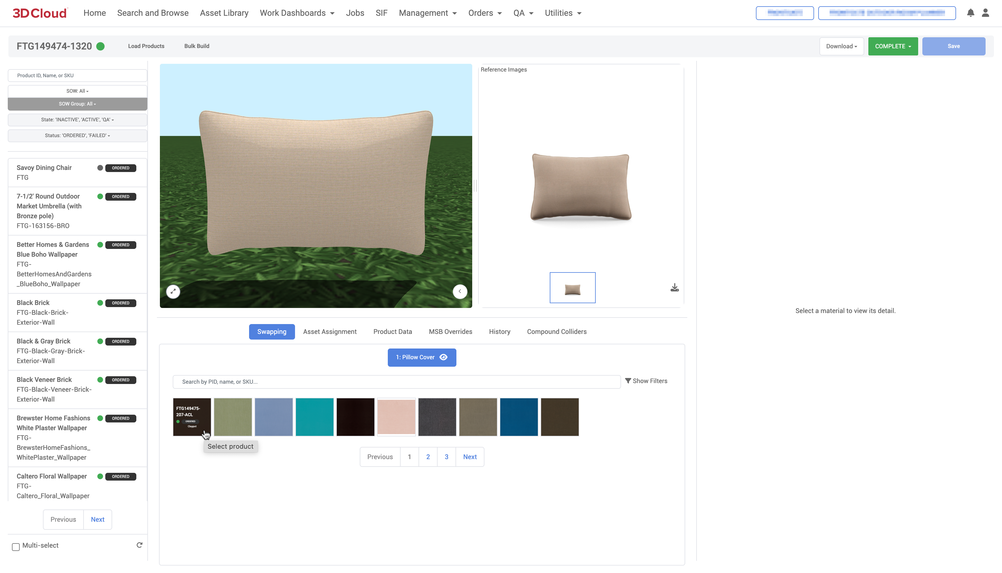
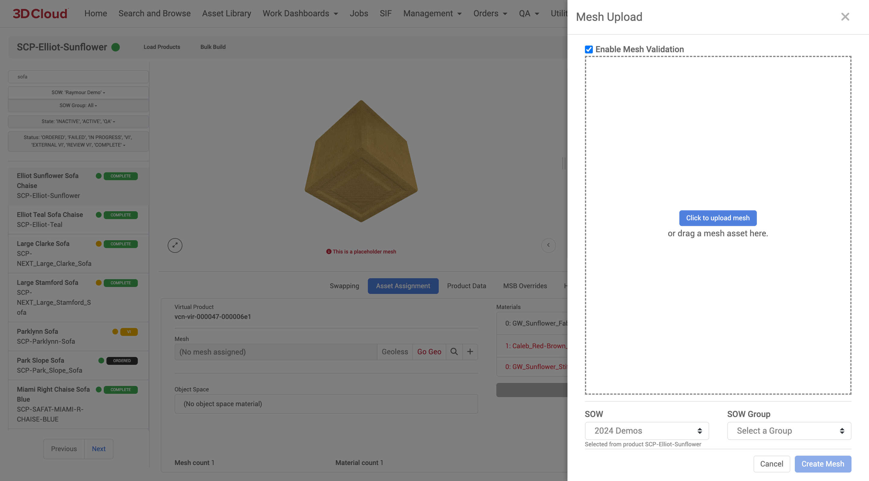
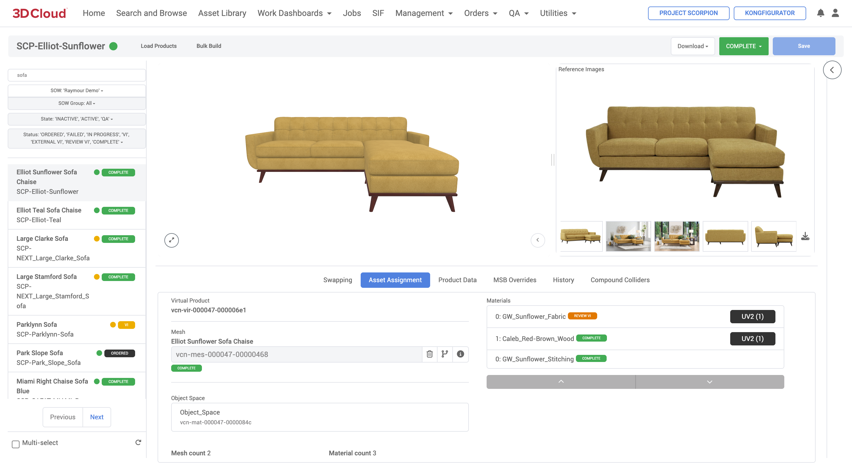
Asset Assignment
Adding a New Mesh
Once a product is loaded or selected, to upload a new .fbx mesh file, click on the plus (+) icon that is to the right of the vcn Mesh input field. Select the Click to upload mesh button, or drag the mesh asset on top of the right panel. Note: At this time the mesh upload only runs through the normal mesh_convert ujs job and so does not handle mesh validation yet..png)
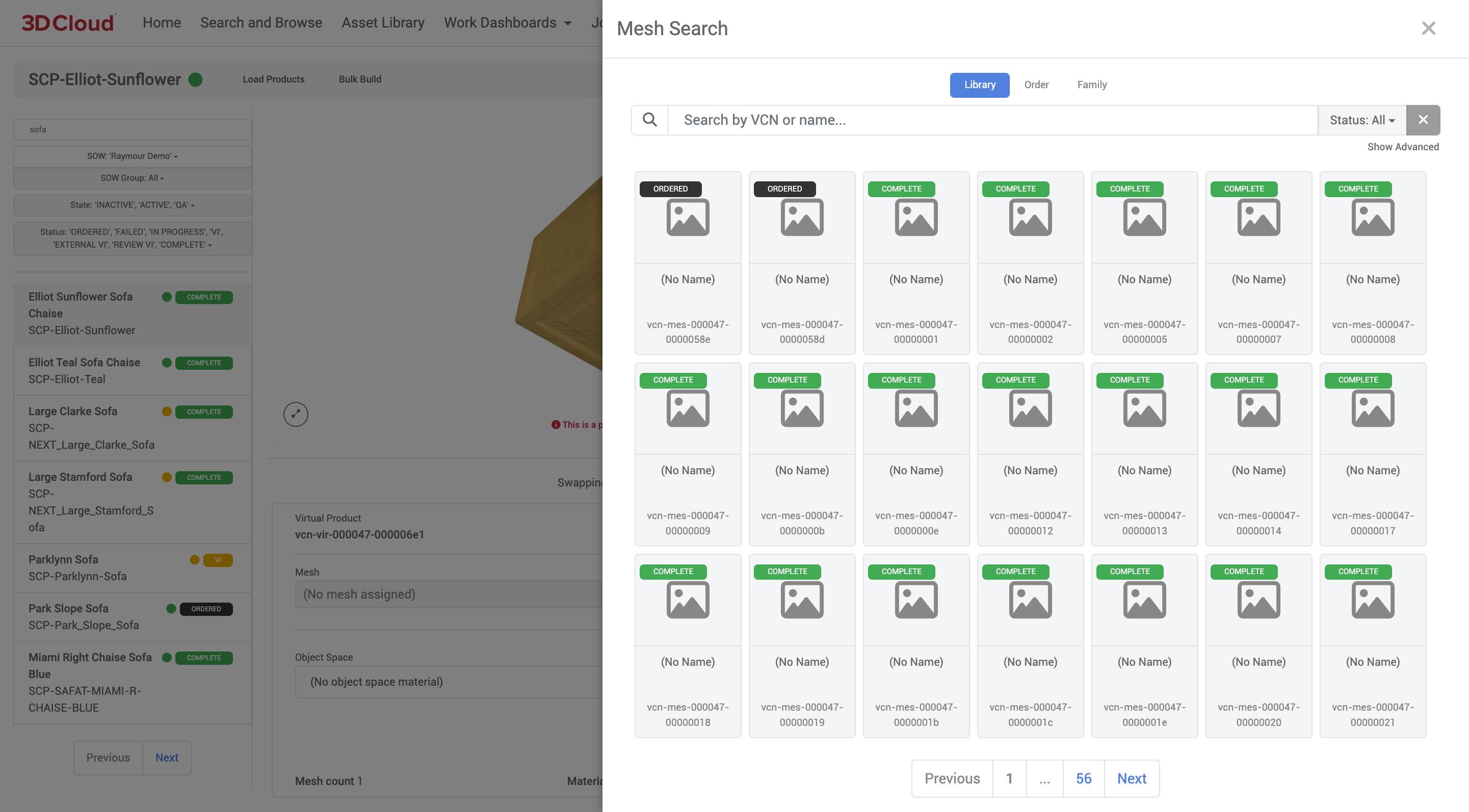
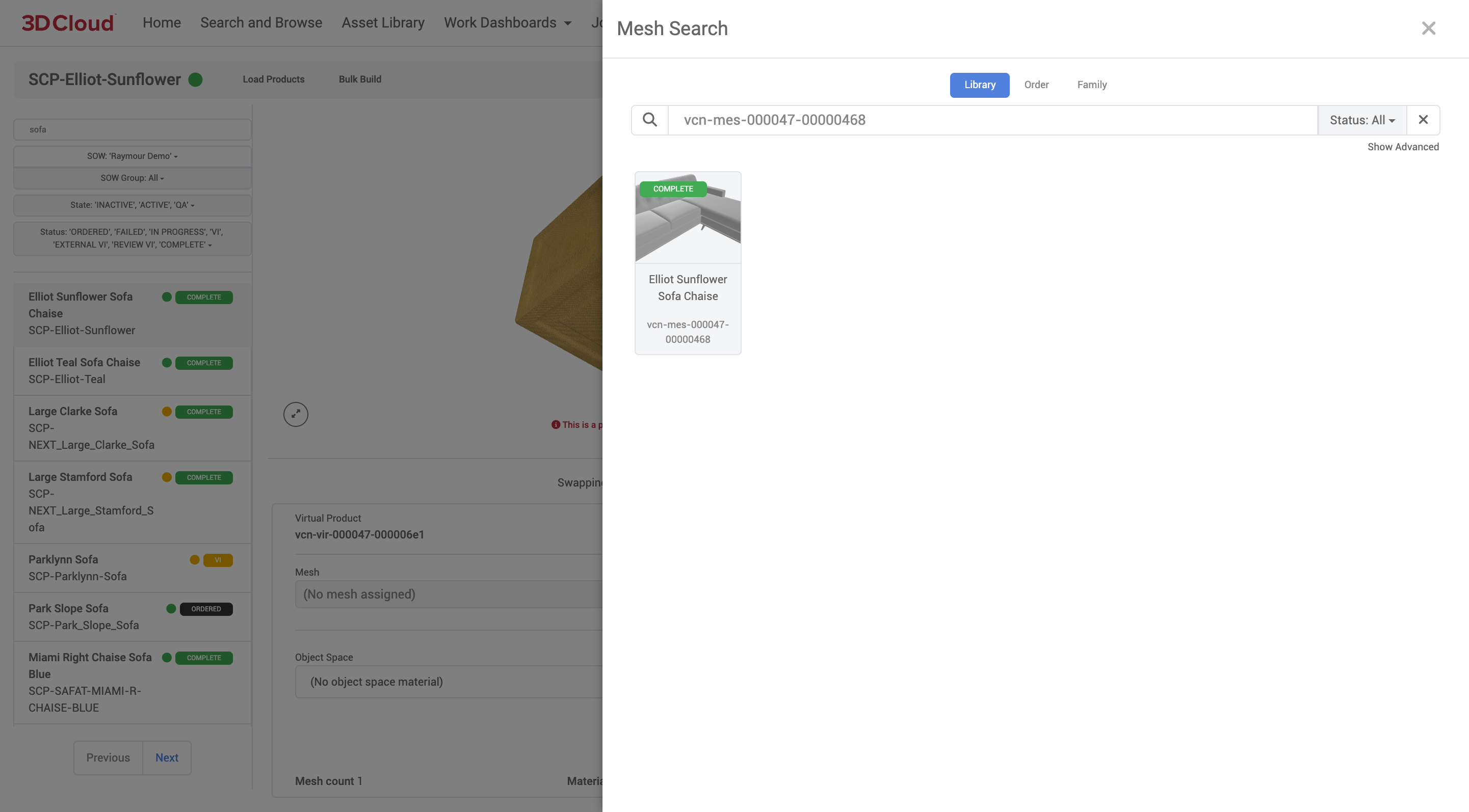
Add Existing Mesh
If you are not wanting to upload a new mesh but instead want to find a mesh that has already been added to the 3D Cloud AMS, click on the Search (magnifying glass) icon that is to the right of the vcn Mesh input field. Once the asset library displays, you will be able to search by name or the mesh vcn and assign the mesh to the product.
Once your mesh assignments are complete, click the blue Save button on the upper right of the page.
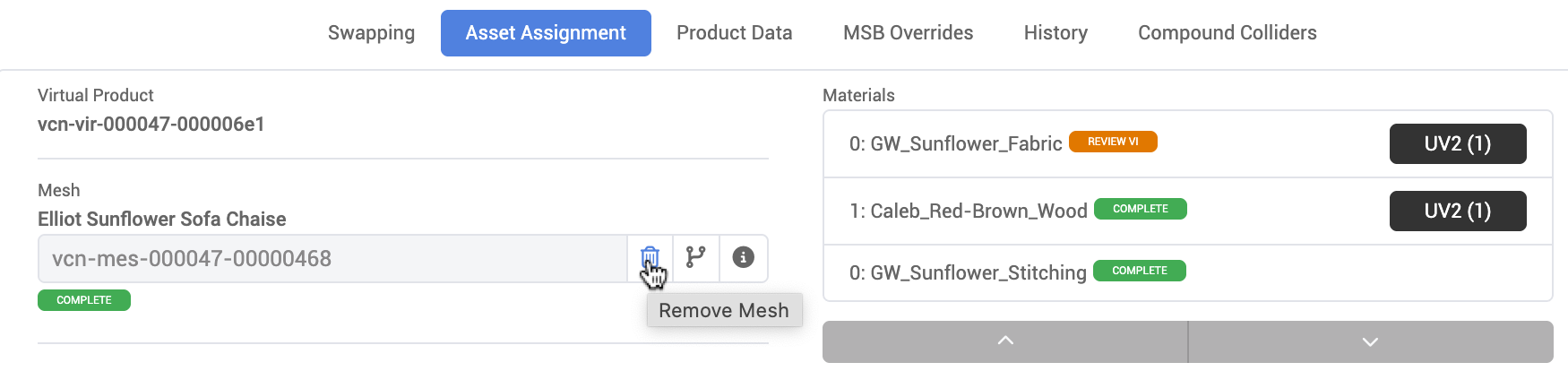
Remove Mesh
To remove a mesh assigned to a Product, you can click the Remove Mesh (trash can) icon to the right of the Mesh input field.
Once your removal of the mesh and reassignment is complete, click the blue Save button on the upper right of the page.
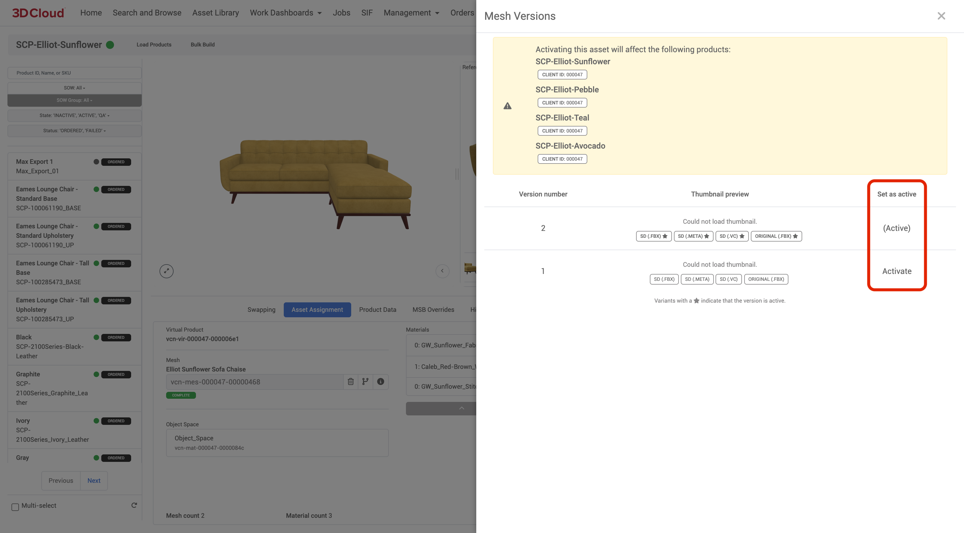
Check Mesh Version
As meshes are updated or changed versions are saved. You can click the Mesh Version (split arrow) icon to the right of the Mesh input field to check or activate different versions of the mesh (where applicable).
![]()
Object Space
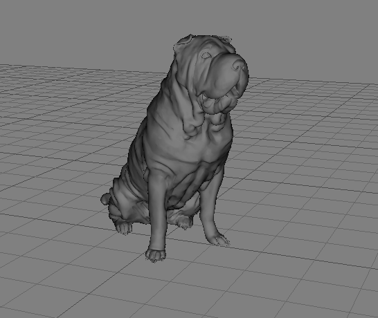
3D Cloud AMS Object Space (OS) maps are a type of 3D texture map used in 3D graphics to store information about the orientation of surfaces in object space. Using our platform, an object space map is created and may be assigned to each virtual product.
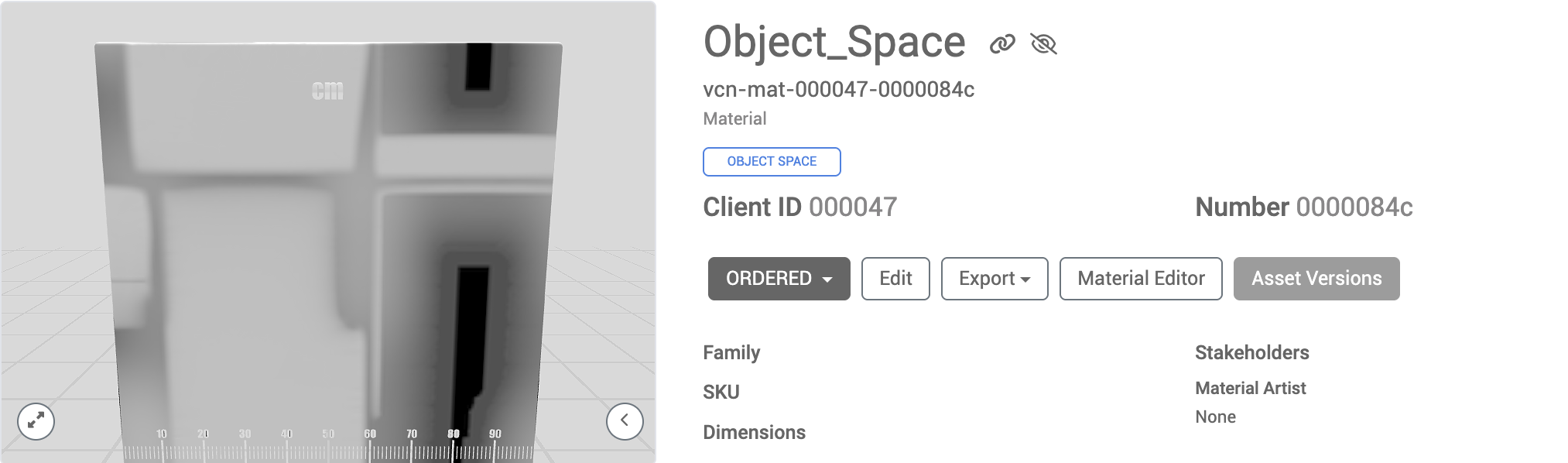
Object Space Map example
The map is used to enhance the visual detail of 3D models by providing data that can be used for effects like ambient occlusion (darkening/shadows where two surfaces join together) or normal mapping (adding depth to materials, like bumps or grooves). Object space maps are added to products to add a more realistic look to the real-time view of products in our 3D Apps.
|
|
3D product real-time view (without Object Space Map) | 3D product real-time view (with Object Space Map) |
.png)
.png)
Add or Create New Materials to a Product
On the Build 3D page or in Product Builder, the Asset Assignment tab (in blue below) will display the mesh assignment field and also the Materials assignment field(s).
Products require materials to be assigned to "Material slots” which correspond to parts of the 3D model. For example, there may be separate material slots on a Sofa that correspond to the back cushions, seat cushions, throw pillows, stitching, frame, legs and floor glides.
When a Material slot is selected in the Materials area, the corresponding part of the 3D model will be outlined in white on the 3D preview.
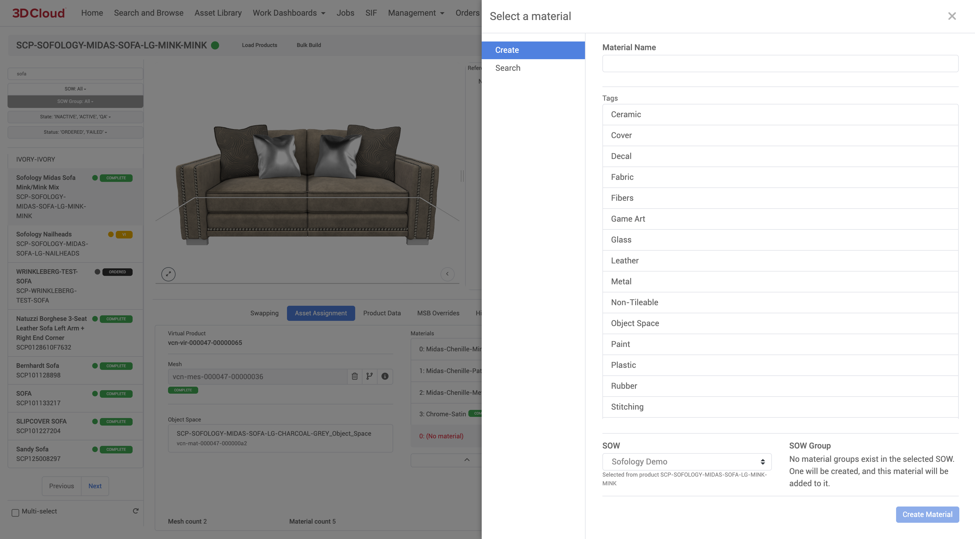
Add New Material
.png)
If no materials are present on the currently select product, you can click on the plus (+) icon within each material slot and either:
Select a material from the asset library by searching:
the Asset Library,
the Assets that were associated with this product at order time, or
the Order or assets assigned to products sharing the same family or modeling group as this product.
.png)
or Create a new material
Other Material Controls
Other material slot controls appear as a row of icons ot the right of each material slot. The material slots correspond to specific parts of the geometry (e.g. cushions/fabric, legs, stitching) on the 3D mesh that require different textures. These material slots are prepared by the artist in the mesh file according to 3D Cloud modeling specifications.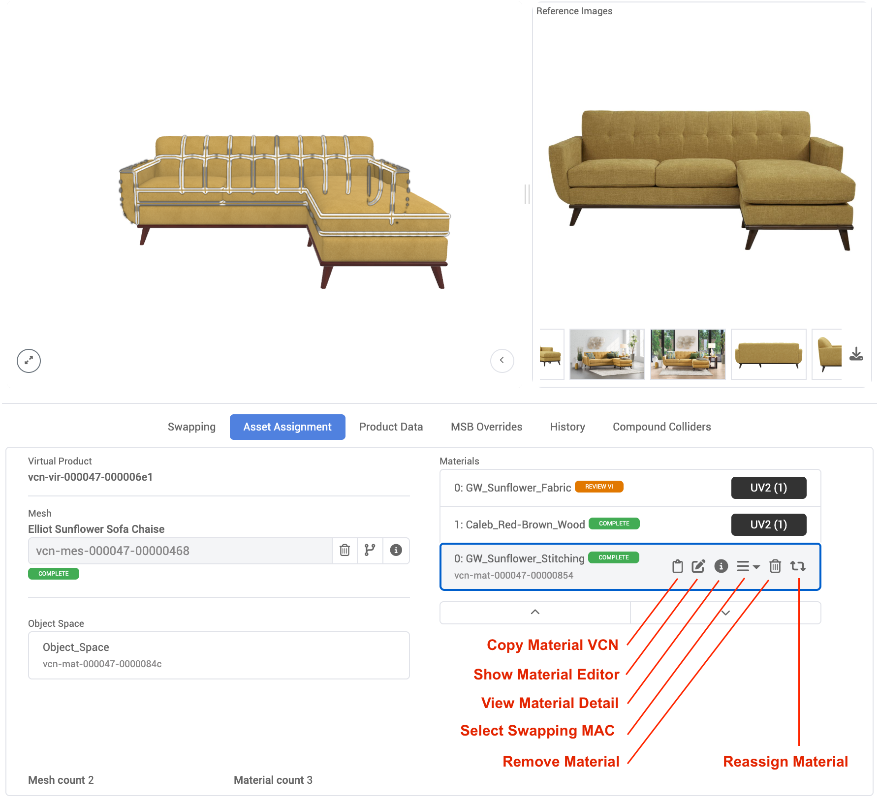
Material Slot Controls | Icon | Functionality |
|---|---|---|
Copy Material VCN | Notepad | Copies the vcn-mat- index number for pasting |
Show Material Editor | Pencil | Links to the Material Editor page for the assigned material |
View Material Detail | Info “i” | Modal window showing Material Details including status, metadata, history and comments, References, Details (Material Texture previews), Impacted Products |
Select Swapping MAC | 3 horizontal lines | Used to set the material slot to a swappable type |
Remove Material | Trash can | Removes currently assigned material from the material slot |
Reassign Material | Rotation arrows | Opens an asset search to assign a new VCN material to the material slot, or create a new one |
Product Data
The Product Data tab displays the Product Name, SKU, Client PID, Categories, DImensions, Color, Buyable, and Stakeholders assigned.
MSB Overrides
Model Space Bounds (MSB) are used to adjust the dimensions and positiong of meshes so they align in a way that is most accurate (e.g. sectional pieces being closer together than their default bounding box alignment). Typically this tab is not applicable to materials.
History
The History tab displays a running record (Date, Time, Author/User email) of status changes to the product within the platform—including when the product was originally imported or created and any state changes (QA, COMPLETE, etc.).
Compound Colliders
Compound colliders are made to override the default box collider for a product mesh. They allow multiple colliders to be specified, which gives more control over collisions.
Features
Use the Add Collider button to create new colliders
Note: Compound Colliders require a Mesh to be assigned to the Virtual Product
Select colliders using the list on the left
Colliders are sorted ascending by their unique ID
New colliders that haven’t been saved will get a negative number (used for temporary reference)
Set the appropriate input fields as needed. Currently, bounds can only be adjusted by the input form.
Note: Currently only Collider Type ‘BOX’ is supported
Delete colliders using the red X button
The visible checkbox will show/hide the colliders
After making changes, use the Save button
If the save button is grayed out, there are no changes to be saved
Note: Changes won’t be saved unless you select the ‘Save’ button!
Product Templates Toolset
Product Templates (formerly “recipes”) allow users to specify a list of rules that can be used to validate and populate product data. Within the Product Template Toolset (formerly “The Bakery”), users can create and manage these templates.
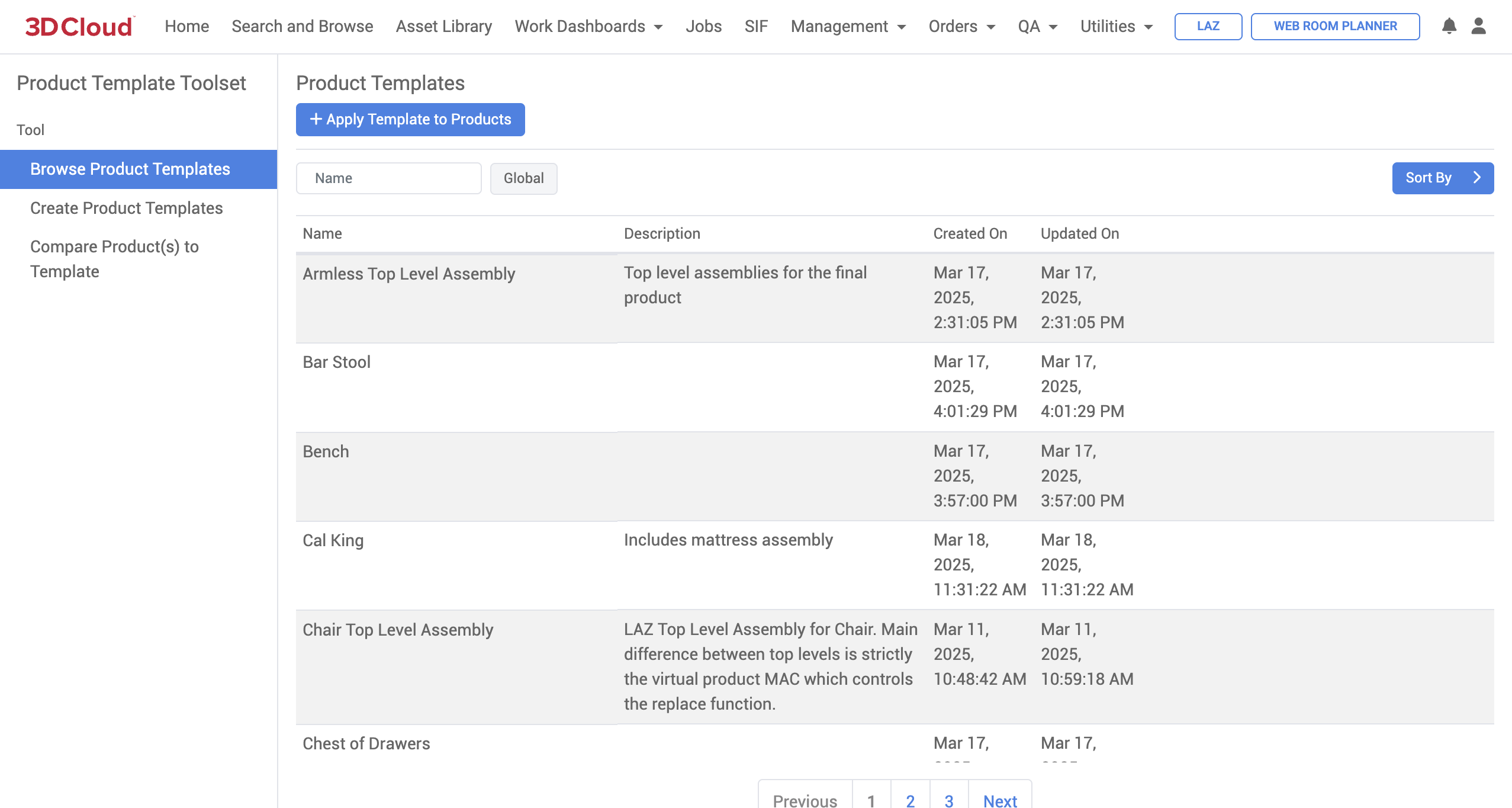
Editing a Product Template
To edit an existing template, click the Edit button while hovering over the template row.

Product data is grouped by entity in a flattened structure, not necessarily representative of its actual nested level in data.
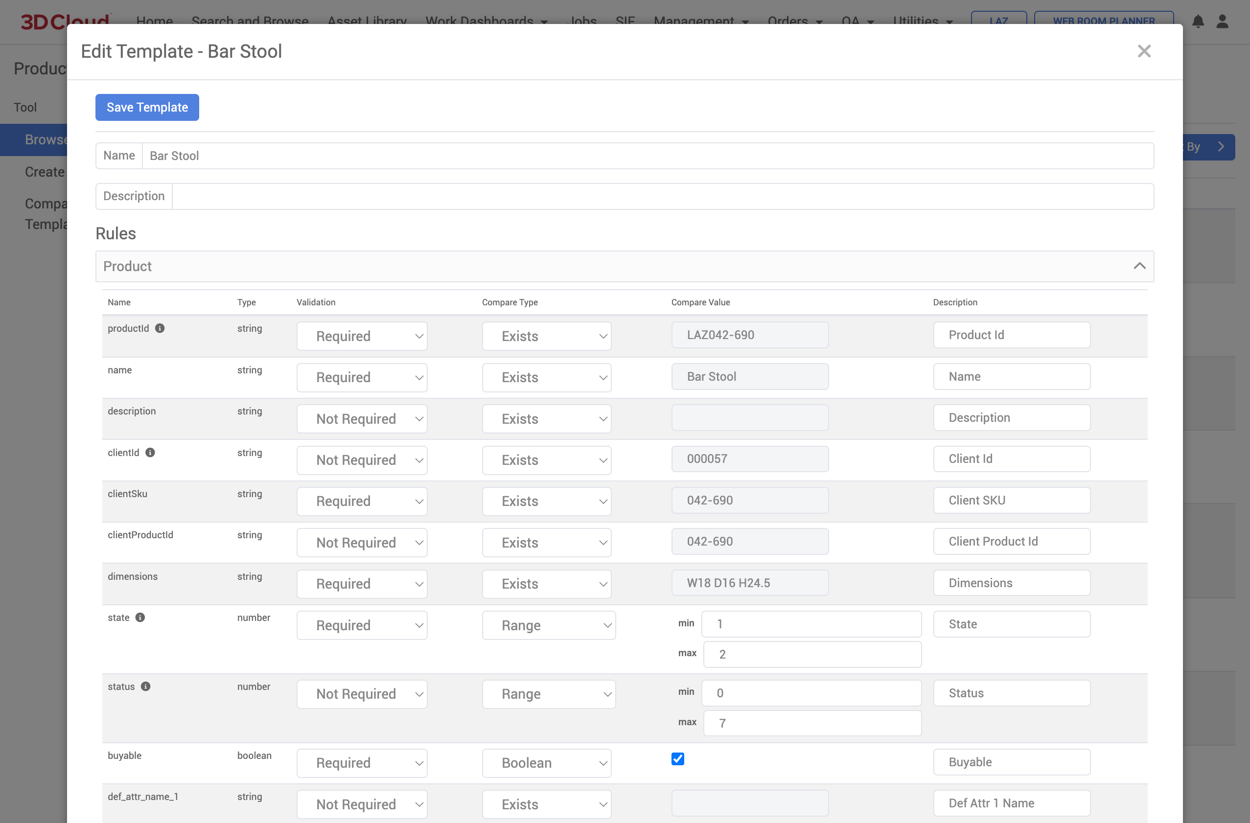
The Validation, Compare Type, and Compare Value input fields determine how data will be compared or applied for that particular property on a product.
Note: Sections/fields with an info icon beside their name will not be applied to products, but they will be used in comparison.
Enabling/Disabling Templates
Click the Disable button to remove a template from lists throughout the application (the order form, for example) without deleting it entirely. Templates can be re-enabled later.
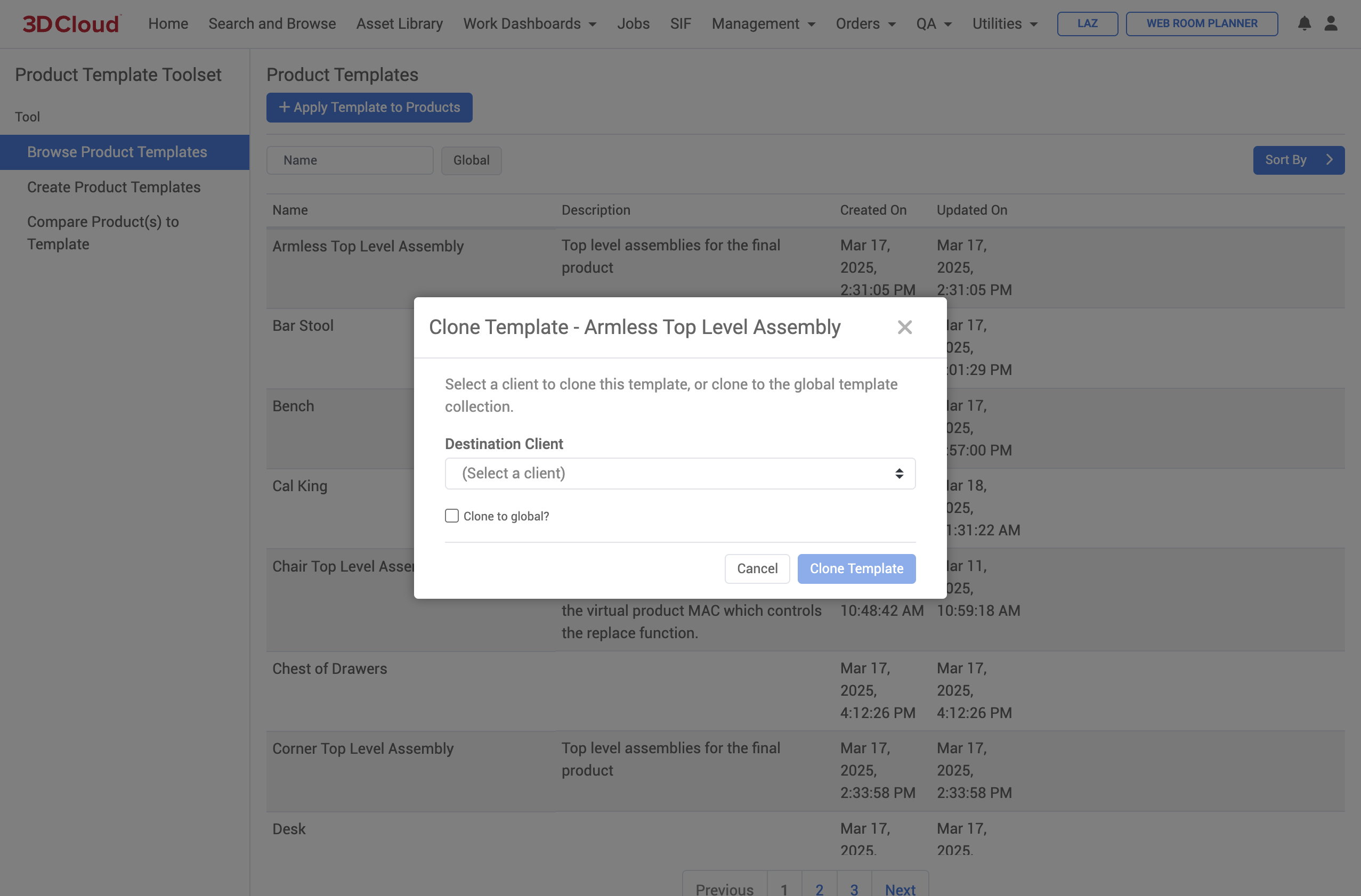
Cloning Templates
Templates can be cloned to other clients, or cloned to the global template library making it available to any client. Click the Clone button to open the cloning dialog.
Apply Template to Products
Product templates can be applied to existing products by clicking the Apply Template to Products button.
Select products to apply the template using Category navigation or Search & Browse.
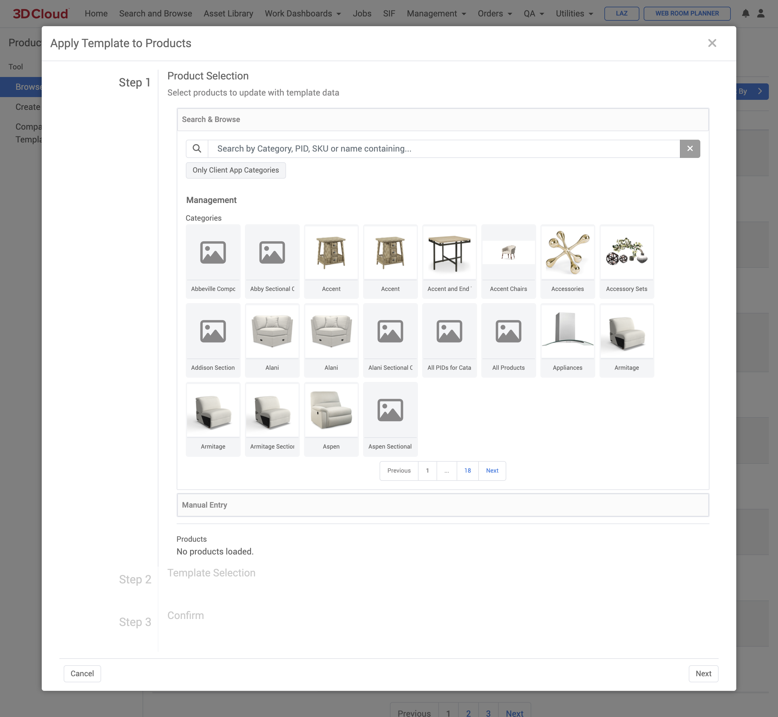
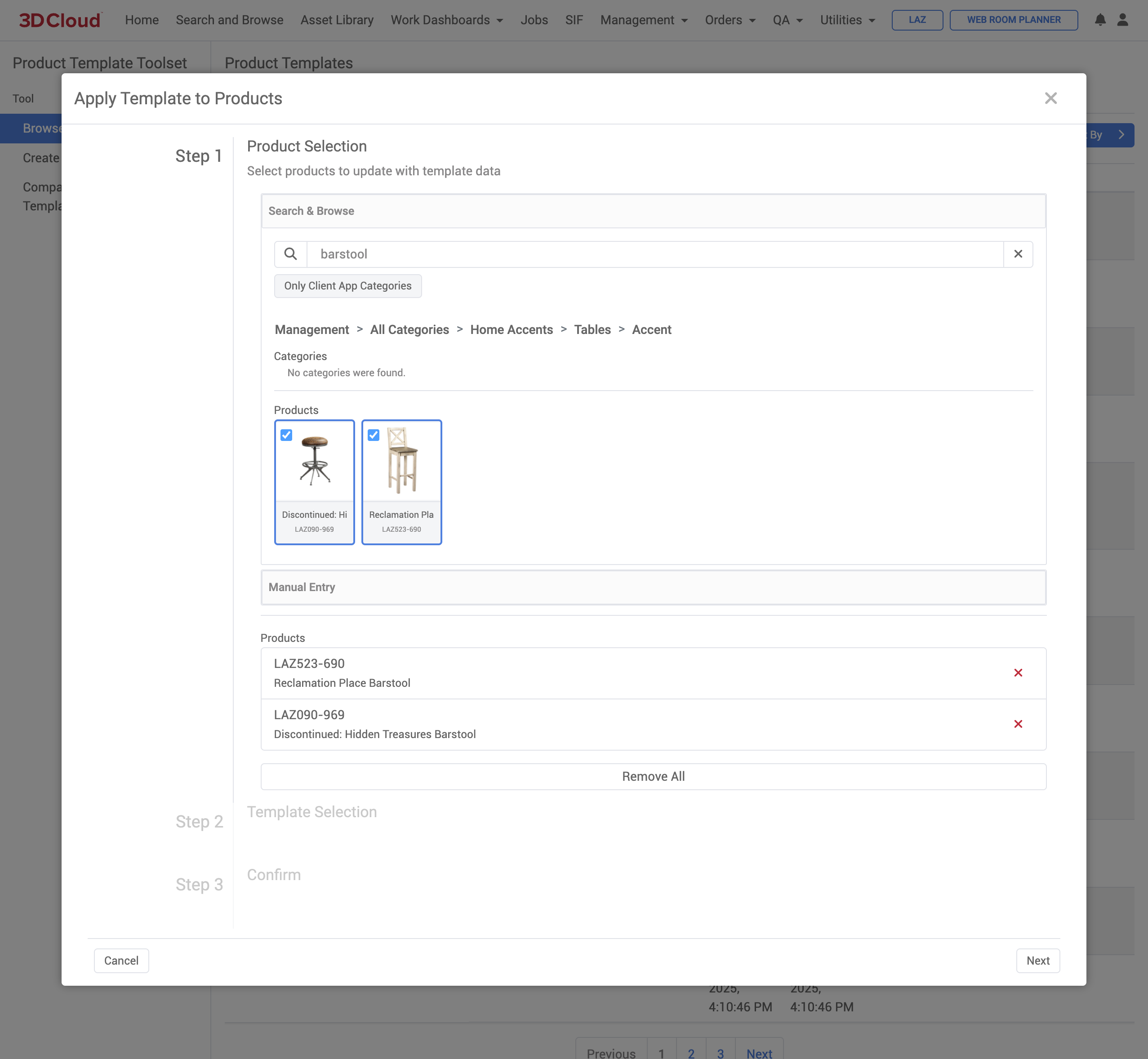
Click the Next button to select the template itself. Note that once a template is selected, users are able to exclude individual fields from being applied by expanding the template detail and checking the checkbox beside the field name.
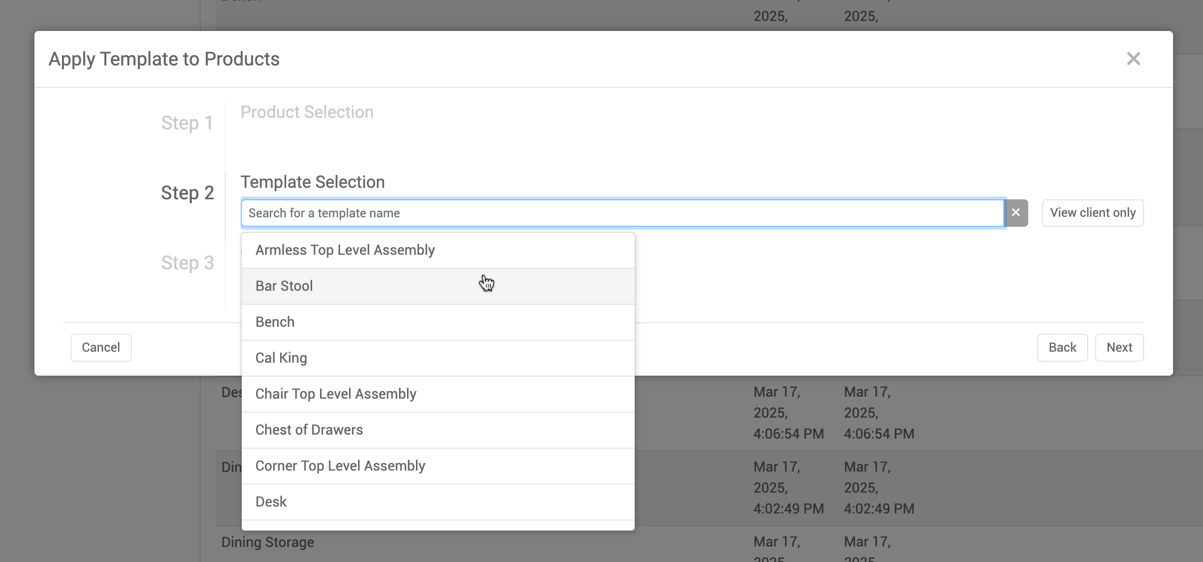
Click the Next button and confirm.
Existing product data WILL BE OVERWRITTEN. Use this tool with caution.
Once data has been applied, a report of warnings/errors encountered in the application process will be displayed. If the Preview Only? toggle is on, product data will not be applied, but the report will still be generated.
Creating a New Template
New product templates are created from the detail of an existing product. Click the Create Product Templates button on the left-hand navigation, then input a PID into the input box.
Some string values in AMS are represented numerically within the template. For a helpful reference, please visit the Product Template Field Enumerations page, which contains translation charts from numbers to strings.
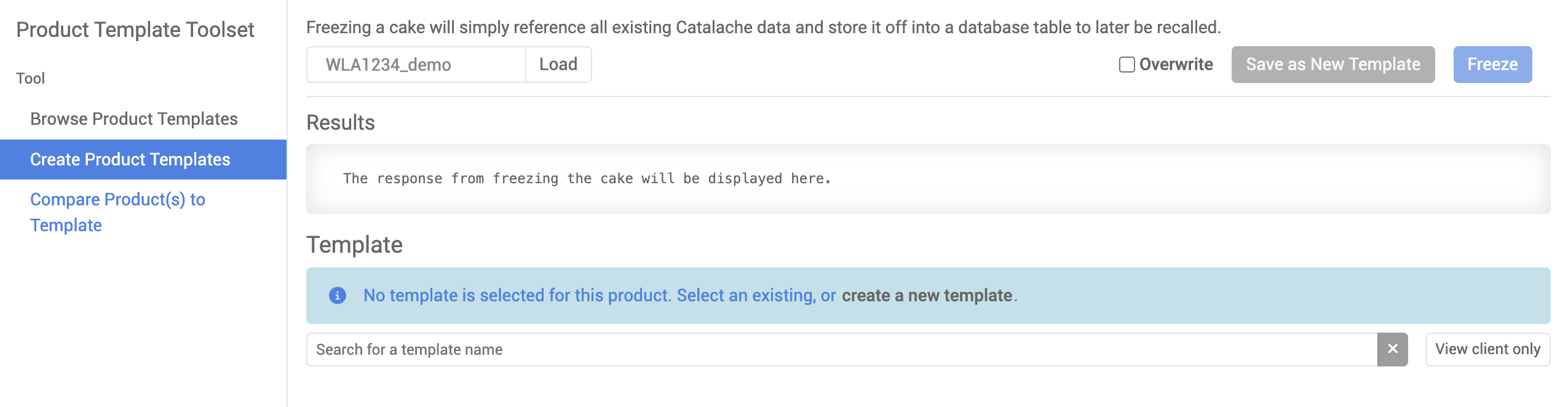
If the given product has previously been saved as a cake archive, and has a recipe associated with it, that recipe will be displayed by default.

In that case, a new recipe can be created by clicking the Create a new template instead text link.
If the product hasn’t been previously frozen, click the create a new template text link to generate a new one from the given product’s data.
.png)
Click the Save as New Template button to create a template without saving the selected product as a cake. Freezing the product will also save the template.
Comparing Products to a Template
Existing product data can be compared to a template (formerly known as a “Taste Test”). Click on the Compare Product(s) to Template tab on the left-hand menu, select a template, select a product ID, then click the Compare button to generate a comparison report. Fields that meet the criteria of the template will be highlighted in green, whereas fields that are out of spec will be highlighted in red.
Fields that require an array of items will be sorted before comparison.
Products can also be compared in bulk. Click the Bulk Compare button on the top-right to open the bulk comparison dialog and generate a spreadsheet comparison report.
If the Include perfect ratings in results? toggle is off, product fields that meet the template criteria will not be included in the resulting export. If a product fully meets the spec (a 100% rating), the exported report will not include a separate sheet for that product.
Snappy
“Snappy” (also known as Snap-To-Mount-Points, STMP) is the tool used to visually fine tune the way two or more products/components connect together into an assembly. Examples of these types of assemblies include sectional sofa pieces, monitor arm components, pillows on top of sofas, etc.
The goal of Snappy is to position the products as you want them to appear in the final client application and then have the system automatically Calculate Mount Points and save this Mount Point metadata with the products—important positioning information that is used for configurable assemblies like sectional sofas.
Using Snappy, users can position products in space relative to each other, add mount points (if they are to “snap” together) using a combination of the 3D Viewer and data entry fields.
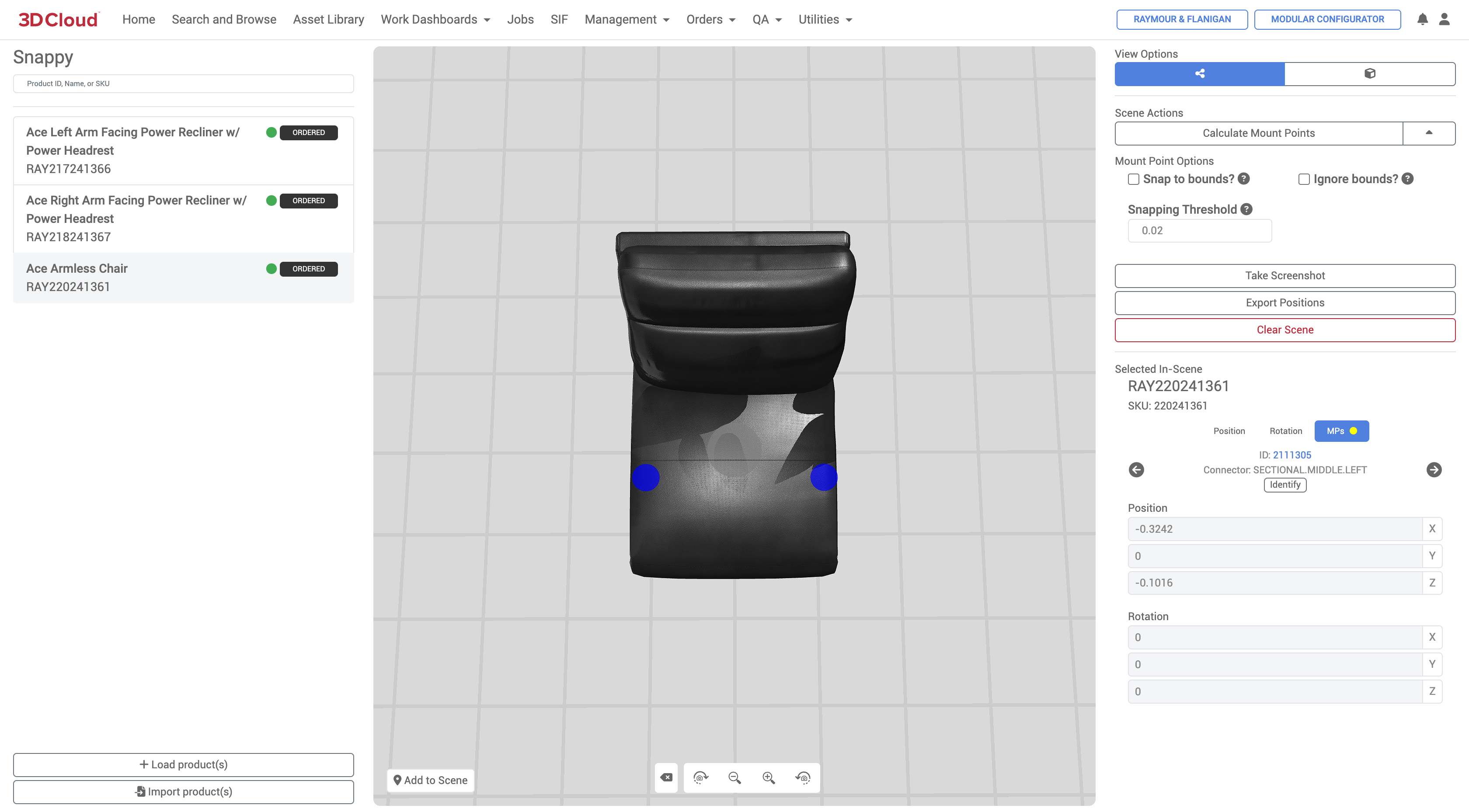
Load Products / Add to Scene
To select multiple products (by Product ID), click the “+ Load product(s)” button and enter Product ID or browse from a specific category to load the products into the tool. To add the product to the 3D viewport, select the product on the left panel and select the “Add to Scene” button in the bottom left of the 3D viewport.
The first product loaded becomes the "root product" (its mount points won't change). When creating Sectional furniture assemblies, often the Armless Chair is used as the root product.
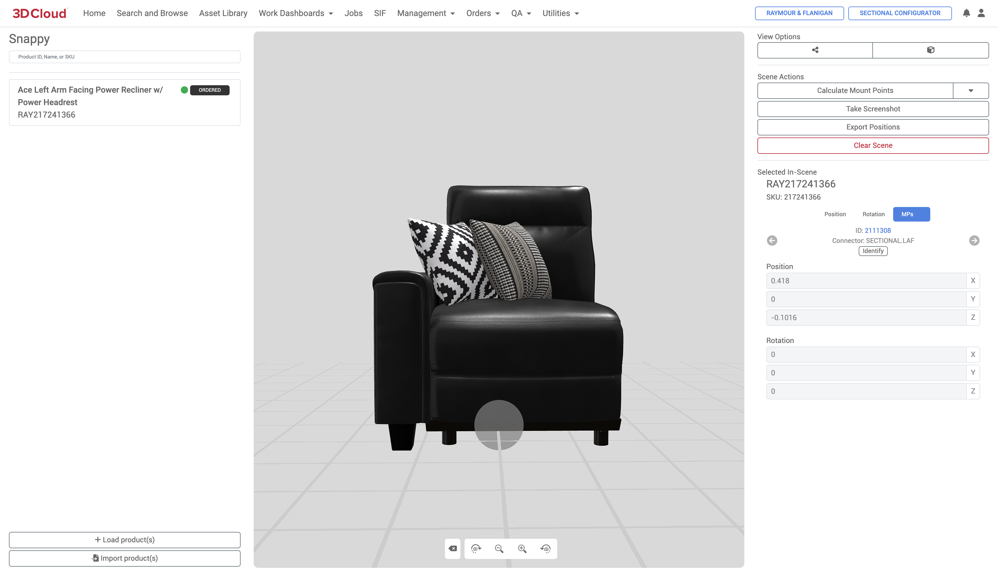
When products are added to the scene, you will see a gray dot indicating the position of the Pivot Point of that particular 3D mesh. Blue dots indicate mount points (where things can attach).
Import Product(s)
Using the Import product(s) button, You can import existing products/components with existing position Pivot and Rotation values directly into Snappy via a spreadsheet upload.
A screenshot of an example spreadsheet is below. This sheet can be generated from an existing product configurator using the Create 3D Components → Export Components button in Product Configurator.
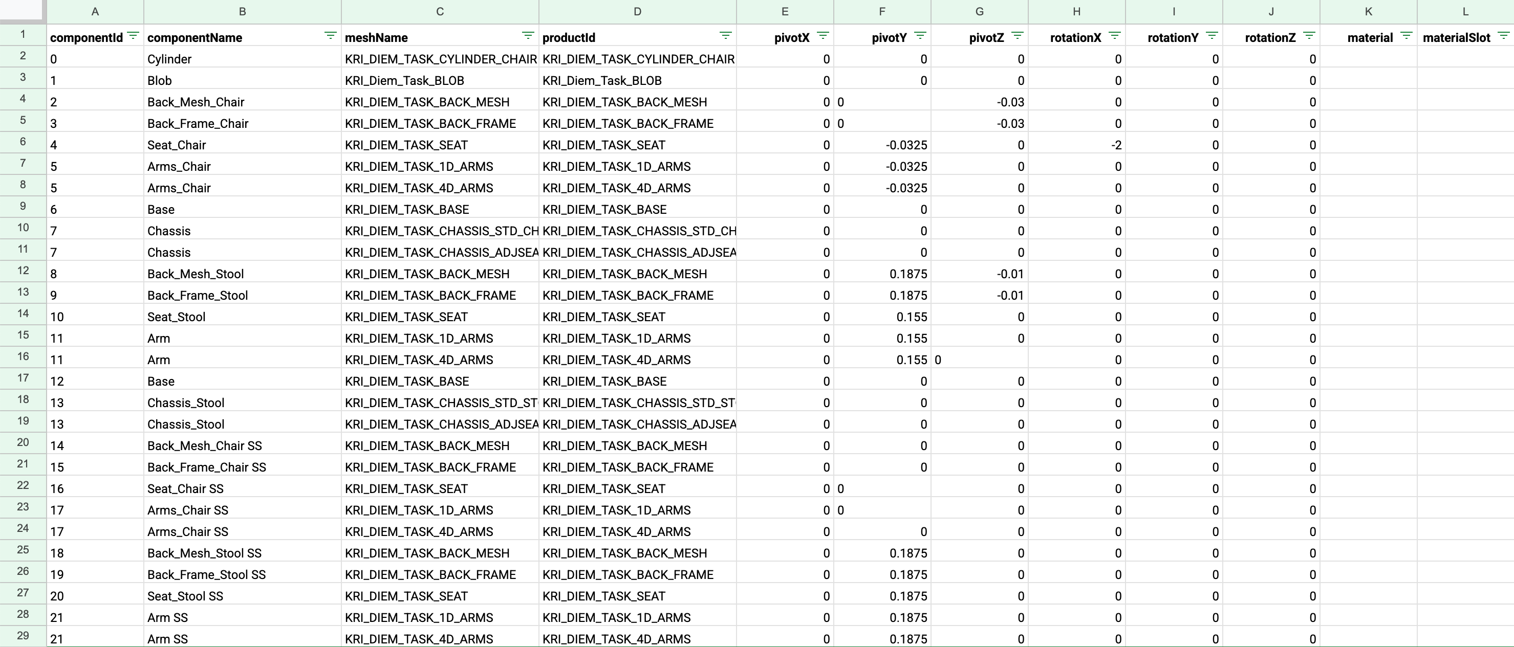
Example Import product(s) sheet
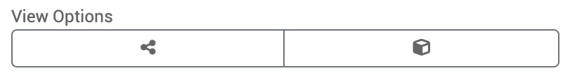
View Options
There are two options for the 3D Viewer:
Toggle Mount Points View (nodes icon) Shows/hides mount points on the model indicated by a blue dot.
Toggle Model Space Bounds View (box icon) Shows/hides a translucent box around the outermost bounds of the object. Helpful for placing objects in relation to each other. The bounding boxes for different products in the viewer will turn red if they overlap.
Calculate Mount Points
The Calculate Mount Points button calculates the positioning information based on the product dimensions and mount points and saves the visual positioning data back to the system.
.png)
Calculate Mount Points Confirmation Dialog shows Old vs. New Positions before saving changes
Mount Point Options
Take Screenshot
Takes a .png screenshot of the current 3D viewport which is downloaded via the browser. The screenshot is useful for…
Export Positions
Exports an .xlsx file containing the productID, pivot coordinates (X, Y, Z) and rotation values (° degrees X, Y, Z) for all products in the scene. This feature is useful for importing back into the Assembly Editor and vice-versa to ensure accurate product/component placement when navigating between those two tools.
Clear Screen
Clears the 3D viewport of all products.
Adjusting Data (Position, Rotation, MPs)
Data adjustments input fields are provided for accurate placement of product positions as well as rotation and mount point data.
Position | The X, Y and Z coordinates of the product or component’s pivot point relative to the 0, 0, 0 origin of the assembly canvas |
Rotation | The rotation value of the product or component |
MPs | Mount points |
Spec Manager
The Spec (Manager) section in the 3D Cloud AMS is a comprehensive system for defining and managing product specifications. It encompasses both building specifications and providing enhanced validation tools for products. A Spec is the highest level definition of what data a product needs, and are typically created by 3D Cloud SMEs to support enterprise clients.
When a product is being activated or validated to see if it is complete, or has regressed, we validate it against the entire Spec.
Specs can be generic across all clients, or specified down to a specific client. A Spec that is built for a specific client can also be generalized across clients in the future if needed.
Primary Use Cases
Ensuring data completeness for products in applications
Standardizing data requirements across product types (e.g., standard floor products, wall products)
Managing product data validation workflows
Troubleshooting specific product data issues
Maintaining consistent data standards as business requirements evolve
The tool essentially serves as a quality control and data governance system, ensuring all products have the necessary information to function properly within 3D Cloud applications.
Core Components
Specs are composed of:
Templates - Defines what data is required, documented in actual spreadsheets that are filled out in order to create a product.
Building blocks - Specific data components within templates
A spec can have one template with one building block, or many templates with multiple blocks
Key Features
Spec Creation and Management
Specs can be assigned to regular products or virtual products
Each spec has a unique name used for product assignment
Can be marked as client-specific if needed
Includes documentation URLs linking to Confluence specifications
Validation Products
Validates that products meet their assigned spec requirements
Prevents tasks from being marked "Done" if data doesn't match spec requirements
New validation tool checks all products against their assigned specs and identifies missing data
Task System Integration
Each Template within a Spec generates tasks for associated products
Tasks are created when products are imported and assigned specs
Integrates with existing task management workflows
Reassignment Functionality
Products can be reassigned to different specs if business rules change
Automatically handles existing tasks when reassigning (moves incomplete tasks to "done" and generates new ones)
Can reassign by category, MAC, SOW group, or manual product ID entry
Stores
The Stores section of the 3D Cloud AMS is used to maintain a database of stores that can be used in a variety of 3D Cloud client applications, including top-of-funnel tools to drive location-specific traffic to the Kitchen Designer.
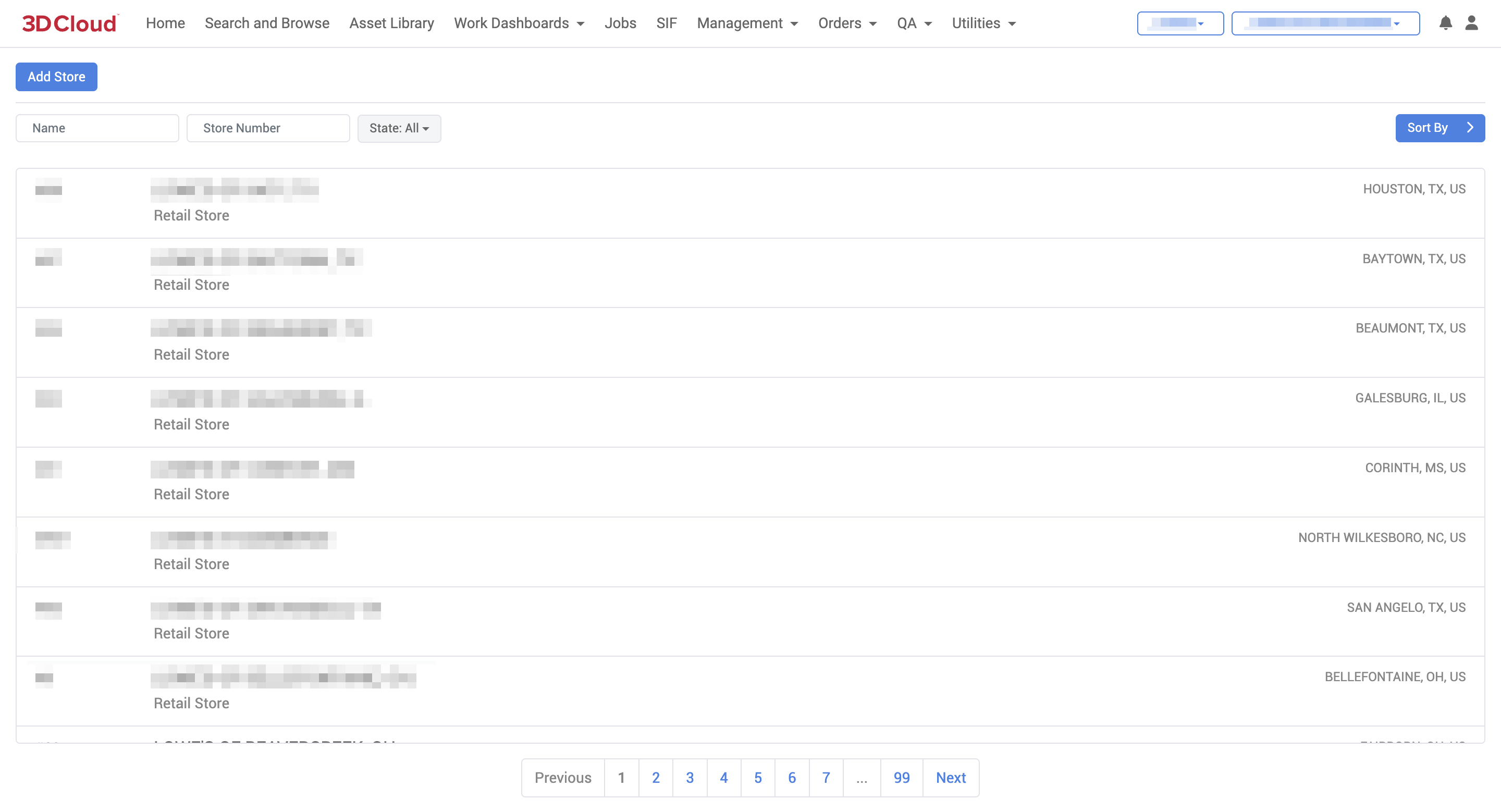
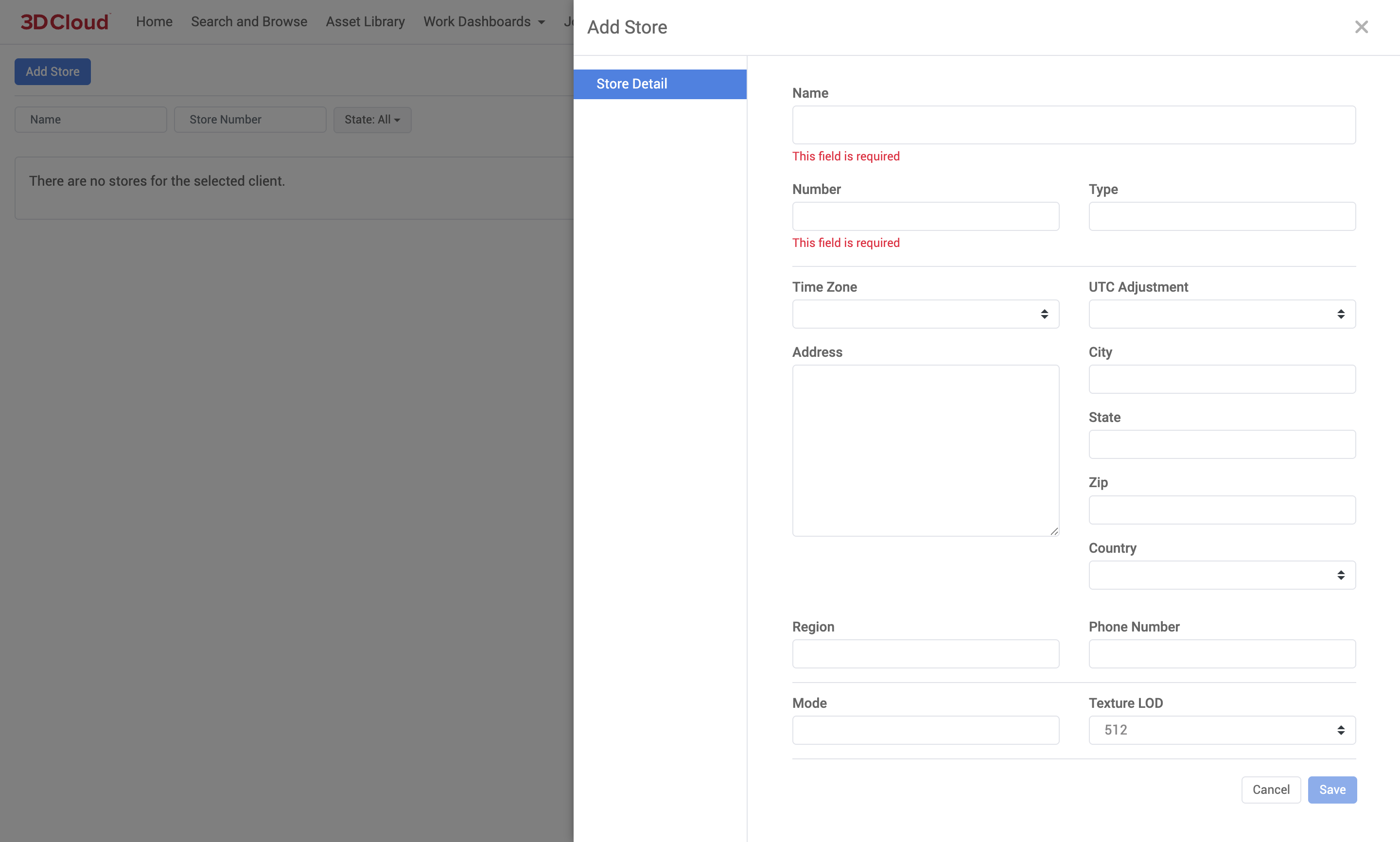
Add Store
A Store can be added to the client, and assigned a “Number” or Store ID. Additional information including Time Zone, Address, Region, Phone number and other details can be specfied.
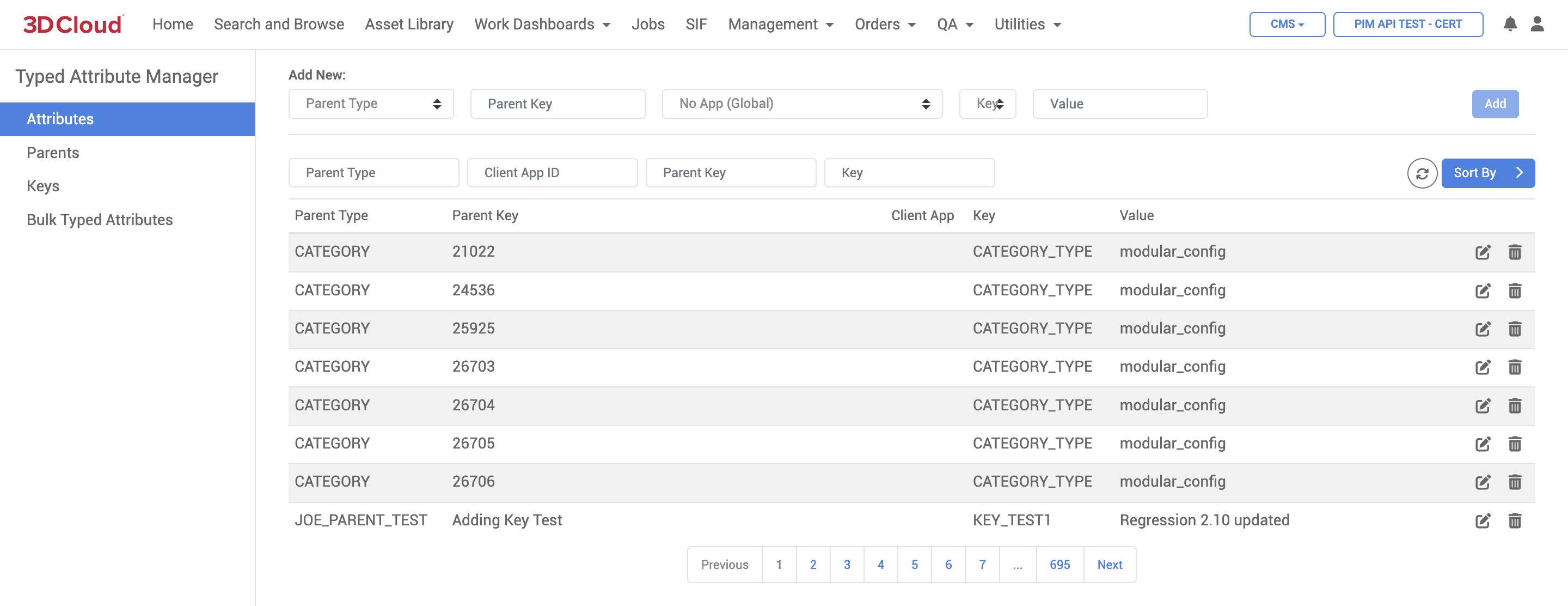
Typed Attributes
The Typed Attributes Manager section of the 3D Cloud AMS is used to define specific characteristics or properties associated with a product or virtual product. It can be accessed via the Management → Typed Attributes link.
A Typed Attribute is a database entry that is used in addition to our standard functional data when we need cross app, features, or properties for a specific function. They are used to define specific properties like modular configurations, orthographic views, or procedural mesh generation. For example, attributes can specify how a product should appear in a 3D view or how it should behave in a modular setup.
For example, a commonly used Typed Attribute is "KONG_CONFIG_ID". This Typed Attribute links a specific configurator created in Product Configurator (Kongfigurator) to Room Planner and/or Modular Configurator. Once this Typed Attribute is added, the Configurator will be able to be searched and placed in the scene of either Room Planner and/or Modular Configurator.
The data necessary to create a Typed Attribute is as follows:
Parent Type
Represents what the Key is. Some examples are PID (Product Id) or VP (Virtual Product vcn), etc. In the case of KONG_CONFIG_ID we are using a PID to connect a Product Id to a Configurator.Parent Key
The Product ID (PID) that represents what will be seen in app and first part of the data that we need to connect.
Example: With Virtual Product VCN, we would use the Virtual product VCN. In the case of KONG_CONFIG_ID, we are using the PID (also known as Dummy PID) that represents the Configurator. That PID will be categorized and searchable in Room Planner/Modular Configurator. Once found in app's search and browse and placed in scene it will place the entire configurator with steps and options.Client App
The App for which the typed attribute is affiliated with. When left blank, it is global, meaning the entry can be used in any App. The majority of Typed Attributes are used globally.Key
The type of value that we are connecting the Parent Key to.
Example: If we are connecting the Parent Key to a configurator, KONG_CONFIG_ID means the Configurator's Id Number.Value
The value is what we want the Parent Key to populate, be connected, or added to when used in various app or various.
Example: For KONG_CONFIG_ID this value is the Configurator Id. This configurator Id is the unique number/letter sequence that is automatically given to a configurator when built. When it's Parent Key is placed in scene the back end knows to pull and populate a specific configurator.
Orders
The Orders section of the 3D Cloud AMS includes tools to create and manage the ordering of 3D content. The goal of an Order is to request work to be done—specifically, the creation of new virtual Products, Mesh and/or Material assets to be used in a client application.
The 3D Content Pipeline
Ordering is the first step in an overall 3D content pipeline process which includes these major phases:
Client Technical Onboarding Client stakeholders are trained by 3D Cloud on all requirements for orders, assets and data, often accompanied by subject-matter expert demonstrations and the setup of template data structures. Orders are placed in the 3D Cloud AMS system after onboarding.
Discovery Based on orders received, the 3D Cloud Data/Business Analysis Team (or the Client and their assigns, if doing self-service) gathers and checks required reference images and data for completeness and separates orders into batches by common types (Products, Meshes, Materials, Decals, etc.)
3D Ordering 3D Cloud 3D Leads verify batches, references, request information and assign assets into a Statement of Work (SOW) that correspond to signed work orders from the Client. The SOW can be broken down further into SOW Groups by type, or into smaller groups if a very large order. These SOWs are then assigned to 3D artist studios, can be prioritized and tracked by 3D or Studio Leads. Internal visual inspection of assets as the come in is completed in this step.
3D Building When 3D assets are completed by the 3D studios and approved, the meshes and materials are combined into the final virtual products to complete the “product building” step. New materials are best created in this step by 3D Cloud internal artists as they can be inspected for accuracy combined with the meshes. OS Maps and wrinkles as needed are created for products in this step to improve the appearance of real-time 3D views.
Data Building After the virtual products are completed and approved through visual inspection, they can be assigned (built) into the final client applications (e.g. Room Planner, Product Configurators, etc.) 3D Cloud and Client teams verify that all data is current, accurate and available.
Test and Remediation This is the final step in deploying content to the final client applications. Products are checked in the final applications and any asset or data issues are addressed in this step as it is the final approval from the client to launch.
Ordering Overview
The overall process for ordering products, meshes and materials is summarized below.
.png)
Order Form
Creating a new Order Form is the first step is submitting an original list of products/SKUs with key source data (dimensions and reference imagery). A spreadsheet-based import tool is provided by the 3D Cloud AMS.
Order Breakout
An intermediate step completed by 3D Cloud Data/BA specialists to make sure the order is translated into the correct number and specifics for 3D meshes, materials and other assets. During the process (also called “Data Discovery) redundant assets are identified and remvoed, and validations are made to ensure the right assets are ordered to work properly in final 3D applications.3D Order Review
A final review is conducted by a 3D Lead to check that all required information is provided for 3D modeling by our network of studio artists.Order Placement and Management
Assignment of batches/groups of assets to be created by studios. Prioritization of orders and visual inspection of returned assets happens in this step prior to final product building (preparation for 3D applications).
Order Tracking Dashboard
On the Client-facing view of the AMS, there is an overall status tracker Dashboard on each Order detail page that displays the number of products in the order and their statuses as a single bar graph. This provides a snapshot view of each order’s level of completeness.
.png)
Order Status Tracker in 3D Cloud AMS (Client View)
Specific Order Progress Bar (aka Status “Pizza Tracker”)
Order Summary Status Flow
Various order status flags are tracked in the 3D Cloud AMS. A diagram of the order status flow is provided below. Within the AMS, various actions will trigger the change of status, and these statuses correspond to the status tracker dashboard views.
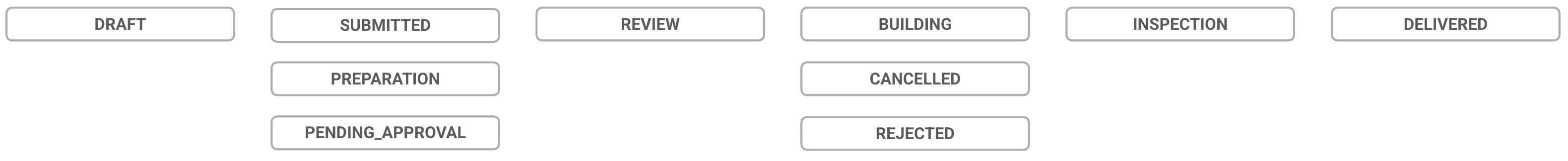
Order Status | Corresponding Tracker Status | Definition/Triggers |
|---|---|---|
DRAFT | TO DO | AMS Order Form started but “Review Order” (submit) button is not yet clicked. |
PENDING_APPROVAL | READY FOR REVIEW | AMS Order Form moves from DRAFT state to PENDING APPROVAL once the “Review Order” button is clicked on the Order Form. |
SUBMITTED | READY FOR REVIEW | AMS Order Form submitted, 3D Cloud Account Manager has reviewed the order for completeness, and clicked the “Place Order” button. Order moves to ACTIVE state. |
PREPARATION | READY FOR REVIEW | AMS Order Form received, Data/BAs doing discovery to define mesh, material, and other requirements |
REVIEW | REVIEW | |
BUILDING | IN PROGRESS or NEEDS REVISIONS | AMS Order Form accepted, Order Breakdown page completed, and SOW/Content Orders have been placed to studios |
CANCELLED | N/A | An order is cancelled for any reason |
REJECTED | FAILED | An order is rejected |
INSPECTION | BEING INSPECTED | Either in internal or external VI (Visual Inspection) status |
DELIVERED | COMPLETE | All content for an order have passed inspections and is complete |
Key Facts About Orders
Processing orders requires participation and “virtual hand-offs” that are handled by status changes between the Client, 3D Cloud Account Management, Data/BAs, and 3D Artist teams.
The status of Orders placed can be tracked on the Orders page, or the AMS Client Home page. The displayed percentage completed is calculated by the number of assets with each progress status over the total assets ordered.
Orders are input into the AMS using our built-in request Create Order Form (see “Create Order” below), and larger orders can use a batch input spreadsheet template.
Orders also include the upload of client-supplied reference images or document assets that are organized by SKU.
When Orders are finalized, Product IDs (PID) are automatically assigned by the platform to the SKUs ordered.
Every Order received into the system will be typically associated with a Statement of Work (SOW), which is a document created by the Account/Sales team name assigned for billing/tracking purposes.
Statements of Work can be broken down further into SOW Groups, which are batches of like asset types separated into one more more groups for organization and production purposes. Typical SOW Groups may be separated out as follows:
Products (Standard Product IDs)
Meshes (UVs)
Meshes (Game Art)
Materials
Assemblies
Dummy, Container, Material or Component Product IDs (for configurators)
SOW Groups can also be used to break up very large orders into groups by asset volume (e.g. multiple SOW Groups will be created with approximately 100 assets per group).
Every Statement of Work should have a Work Order Number associated with it, recorded in the 3D Cloud AMS for billing and tracking purposes. If Clients are providing their own 3D assets and product building themselves, they may be excluded from this requirement.
Any order can be “Watched” using the “Watch Orders” feature (the toggle-able “eyeball” icon next to an Order name). This ensures the user is notified of specific status changes that occur on that order.
Self-Service Order Management for Clients
3D Cloud Clients may place and manage their own orders within the Orders area of the client-facing version of the 3D Cloud AMS. For Clients managing their own 3D studio vendors, orders can be entered into the AMS and permissions can be granted for studio managers to view these incoming orders.
For clients who wish to handle self-service ordering, product building, configurator building, etc. themselves, we provide training during the client onboarding process.
Permissions
A user will need the Order Creator (3DC) role in order to access the external client-facing version of the Self-Service Order Management Tool. This can be set up by a 3D Cloud AMS administrator.
Dashboard
The Dashboard is the first thing you will see after logging in.
.png)
The Self-Service AMS Home Page (Dashboard) Client View
The Dashboard displays four key areas:
Main Navigation Bar
The links to navigate the tool appear at the top of the page and include a dropdown menu on the right side to access Client Application configuration tools.Product Summary
A summary count of Live Products, In Progress, Ready for Review and In Remediation.
Ready for Review and In Remediation have clickable links to the Visual Inspection Tool.Client Apps
Quick links to switch between applicable Client Apps.My Orders
A dynamically updated list of all Orders for the Client, with a progress indicator showing the progress state breakdown of the number of products in each stage of the order. Default order display is most recent at the top of the list. Clicking on any of the Orders in the list will open the Order Details page for that Order.

Order Progress Indicator
Order Management Through 3D Cloud
For some clients, ordering is handled through 3D Cloud Account Management associates and/or and 3D Cloud Data/BAs. Currently, Client orders might be initiated through SKU lists and/or spreadsheets delivered to the 3D Cloud Account team, but in any case, all orders will need to be input into the 3D Cloud AMS via the AMS Order Form, which can accept an imported sheet in a standard format.
Additionally, all reference images and files from clients are delivered via shared drive links, FTP, email, or scraped from Client websites by pre-arranged 3D Cloud tooling.
Create Order
Accessing the Order Form
To start a new order and access the Order Form, the Create New Order button can be accessed via these locations on the Client and/or 3D Cloud associate views of the AMS.

Client AMS Home Page
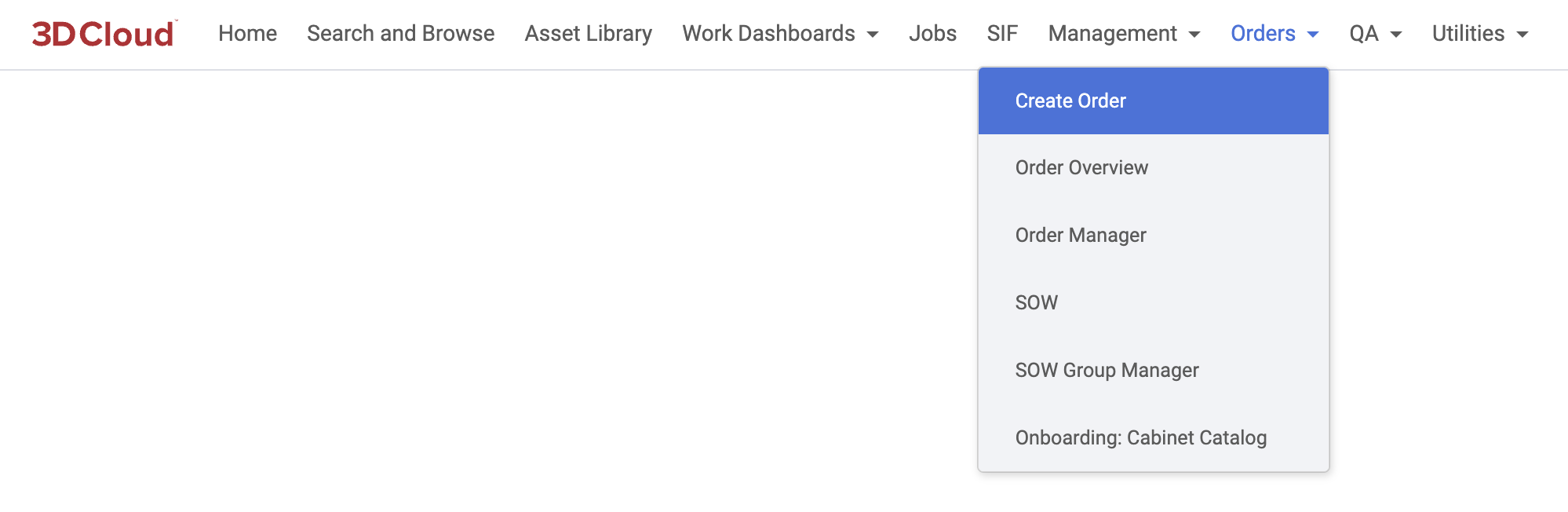
3D Cloud AMS - Associate View
Order Form Step 1: Order Name
The Order Form follows six steps. The first is to provide a name for the Order (ideally the Order name matches a Statement of Work name, and may include a Work Order Number in the title)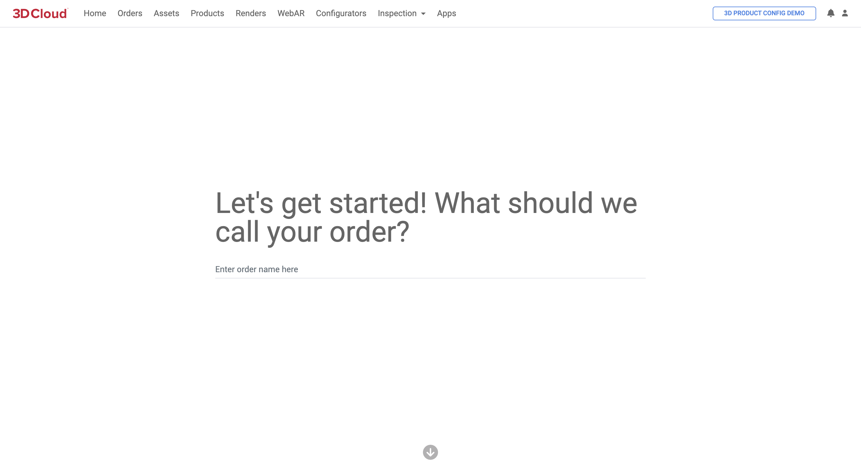
Order Form Step 2: Convert Assets (Under development)
Select “No” when asked if you are have any existing 3D assets you’d like to use for this order.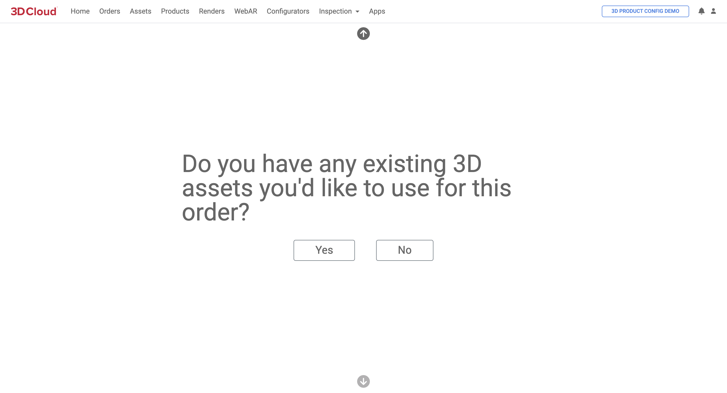
Note: Selecting “Yes” is for a future self-service asset conversion step that is under development.
Order Form Step 3: Select 3D Modeling Quality
Select the quality level of 3D models needed for the order. (Standard or Ultra HD Sculpted)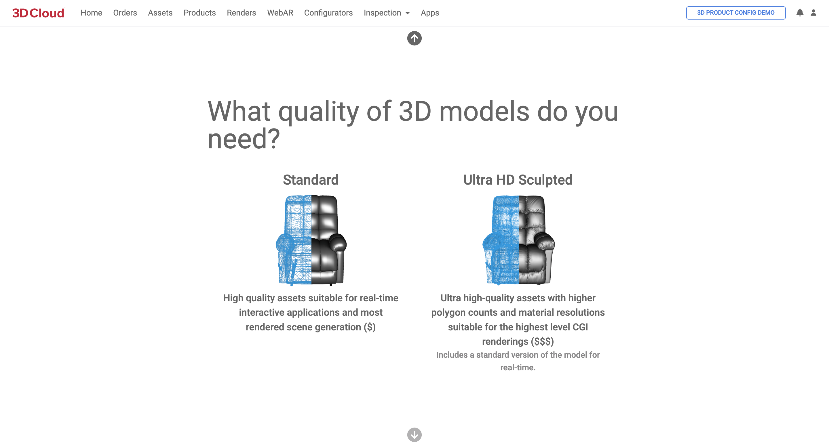
Order Form Step 4: Select Manual Form Entry or Bulk File Upload
Select the “Manual Input” method if you want to go directly to the Create Order form (spreadsheet view).
Select the “Bulk File Upload” if you have a Content Order spreadsheet (.xlsx file) ready to upload. The spreadsheet should be formatted per the 3D Cloud example SKU sheet template.
Note: The “Product URLs” and “Pay 3D Cloud to do it for me!” selections are deactivated.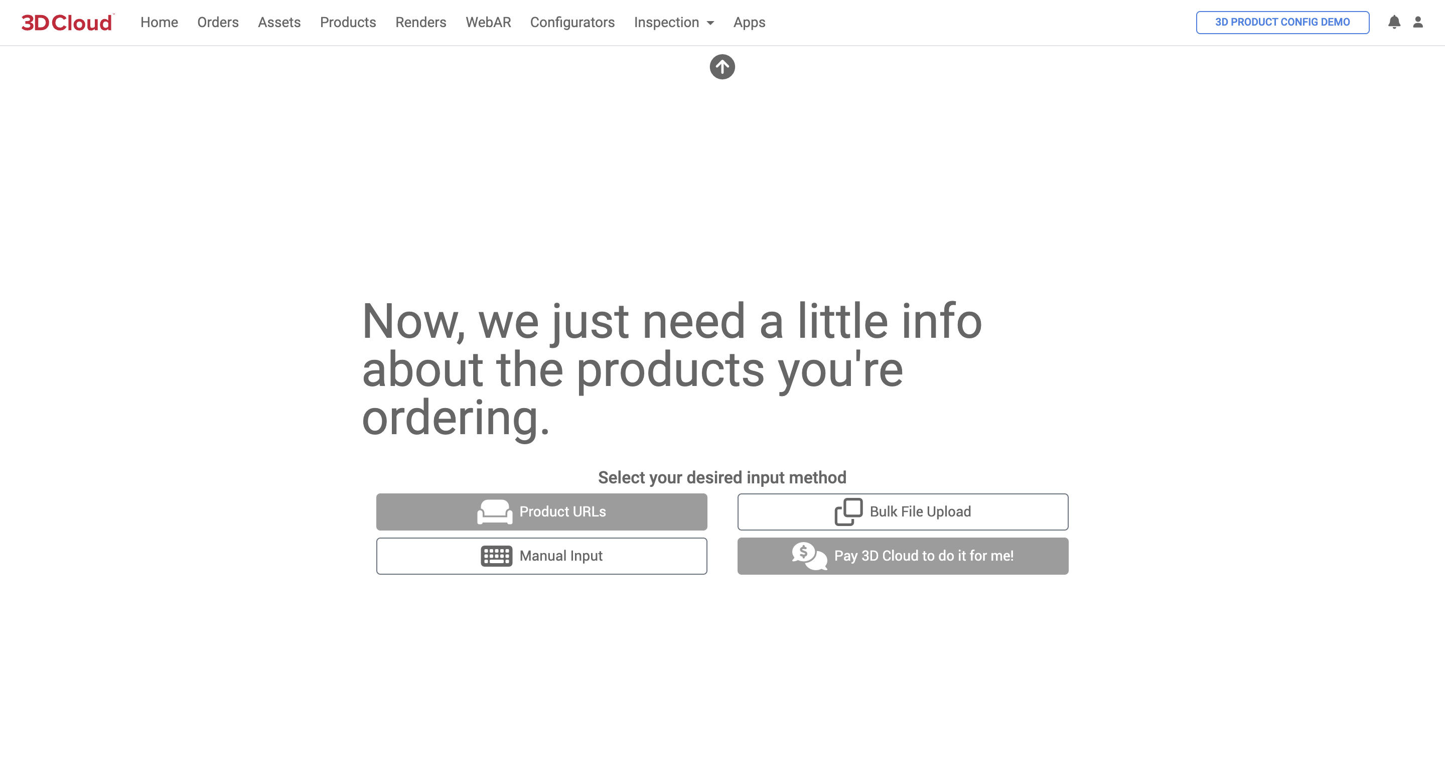
Order Form Step 5: Bulk File (Sheet) Upload
If you clicked “Bulk File Upload”, a modal window with two steps to complete is shown.
The first step is to upload an Excel (.xlsx file) sheet with the order’s SKU list and relevant data to create virtual products.
A template Excel sheet can be downloaded (see below) with specific columns to fill out.
Required information is indicated by the red asterisk character (*) in the Row 1 column headings. The order sheet headings are as follows:
Column Heading | Possible Values | Description |
|---|---|---|
Type * | Product Material/Variant Assembly/Bundle Geometry Only | Product = Any product (or part of product) that needs to be a 3D virtual asset, consisting of 3D geometry and virtual materials applied to that geometry Material/Variant = Materials only Assembly/Bundle = A grouping of existing products with no new geometry needed Geometry Only = Order only the 3D mesh/geometry and object space materials, no other materials needed |
Description | Free text description if needed | |
Name * | Name of Product | |
SKU/Item # * | Client SKU or Item Number | |
Client Product ID | Client Product ID (if applicable) | |
URL | The client website URL of the SKU or Product page | |
Overall Dimensions | METERS FEET INCHES | Specifies the Height, Width and Length in decimal units; |
Dimensions * | Dimension information written out in freeform text, may include additional dimensions relevant for 3D modeling beyond Height, Width and Depth (e.g. Table thickness, arm height, seat height/depth, etc.) | |
MFR SKU/Item # * | If applicable, a manufacturer SKU or Item number; If not applicable or relevant, enter “N/A”, “NA” or “None” | |
MFR Name * | If applicable, the manufacturer name; If not applicable or relevant, enter “N/A”, “NA” or “None” | |
Brand | If applicable, the brand name of the product | |
Reference * | Holds links/names of reference files for the asset | |
Family/Range | The Family or Range name, if applicable | |
Template Product | Dropdown list of available Product Templates for the Client | Specifies which Product template should be used for validating and populating product data for the item (e.g. Sofa, Twin Bed, Rug, Dining Table, Wall Decor, etc.) |
Category | Product category name or AMS Category ID if known) | |
Notes | Free form text for notes | |
Modeling Group | A grouping of products or meshes that should be created together to ensure visual consistency or fit together. This can be left blank where the product or mesh is a standalone type product (no similar products/meshes that need to be matched). |
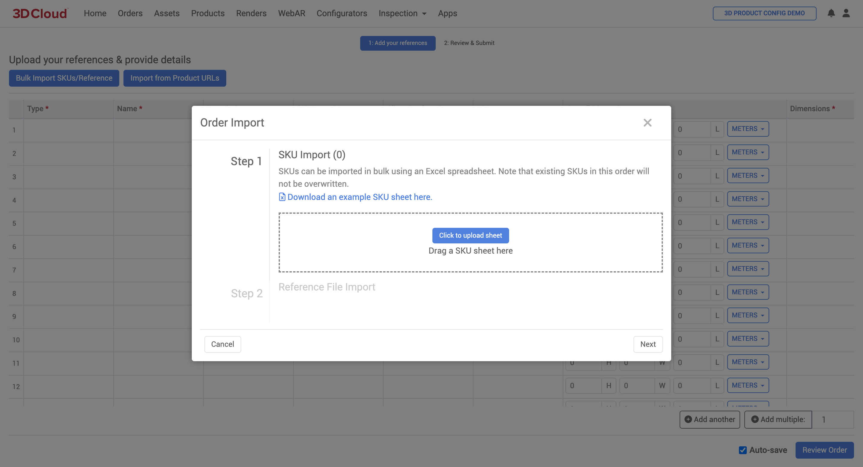
.png)
Example SKU sheet for Order Importing/Uploading
Order Form Step 7: Bulk Reference File Import
The next step in a Bulk File Upload is the Reference File Import step where images or other reference files can be uploaded.
Note these important considerations:
Folder and File Names: The reference files should be placed into folders named with the SKU on the import sheet, or the filenames should be named the same as the SKU on the import sheet. This ensures that the relevant files will automatically be applied to the appropriate SKU, otherwise reference files will be attached at an order level.
Reference images should meet the requirements in the 3D Cloud Reference Image Documentation
Multiple folders can be dragged into the Reference File Import dialog box. There is no need to .zip up the files or folders.
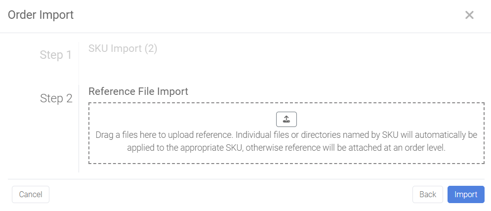
Once uploaded, a list of files to process appears to the right of the Import area. Any files that cannot be attributed to a SKU will be displayed in the bulk upload step as shown below. If a file or directory could not be related/assigned to a SKU, a blue (Unassigned) text will appear. Assign the asset to a SKU using the “Change SKU” link and dropdown menu of SKUs.
Similarly, individual references can be removed from the upload by clicking the “x” icon on the right side of the asset in the list.
Once both the SKU Import and Reference File Imports have been verified to be correct, click the blue “Import” button to submit the Bulk Import information.
Once the bulk import steps are completed, the Order Form will be displayed in spreadsheet format and can be updated manually as required.
When the order form is complete, click the blue “Review Order” button.

Review Order Button to Submit Order
3D Cloud Account/Project Managers are notified (currently outside of the AMS) that an order is ready for review. The Order Summary is reviewed and key information is entered.
Order Name Give the name of the order. Include the Work Order in the title.
Description Provide a brief description of the order for reference
Requested Due Date
Issue Tracking (JIRA) Link This is the 3D Cloud internal Jira link to the Epic for this order
Work Order Number Required
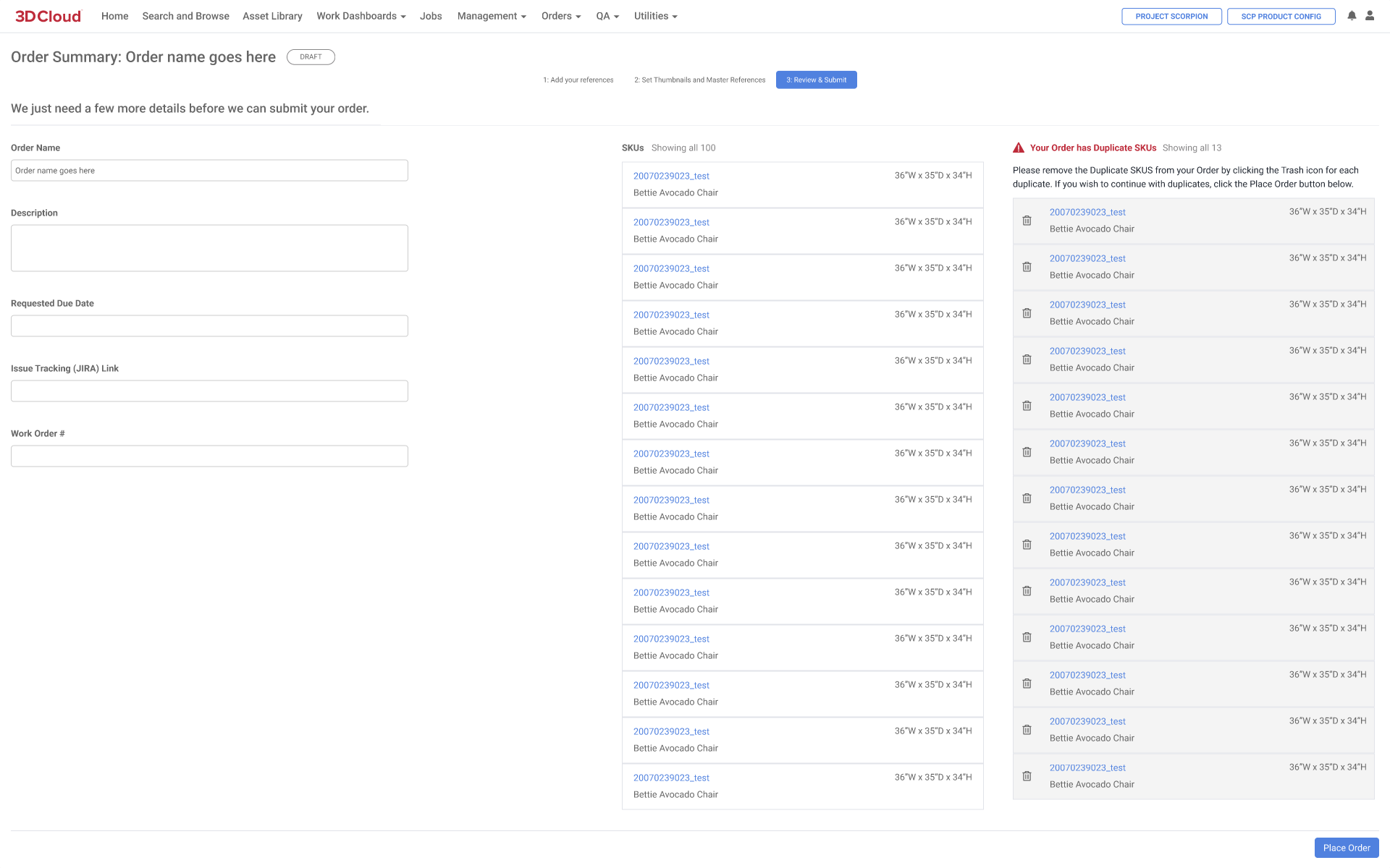
After the order is checked, clicking the “Place Order” button advances the order to the Order Breakdown/Data Discovery step.
Note: Once the “Place Order” is submitted, it cannot be edited or changed.
Reference Image Documentation
When importing Reference Images into the 3D Cloud AMS, there are certain parameters all products need to allow for correct creation of the mesh and materials.
Reference imagery must be large enough in resolution for the artist to be able to use it to build a 3D model.
The following resolutions are usable:
2000x2000px: Fantastic
1000x1000px to 2000x2000px: Great
1000x1000px: Acceptable
The following image resolutions are problematic:
500x500px to 1000x1000px: Approaching Unusable
500x500px or less: Unusable
3D Geometry
|
|
|
|
Examples of good product reference imagery that covers all visible angles. Front, Side (both left and right sides if the materials are different on either side), Back, Top, Bottom (if possible) | |
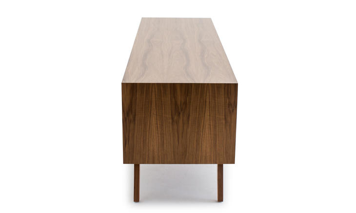
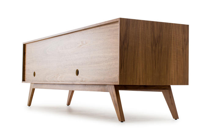
.png)
.png)
When providing reference imagery for geometry (a 3D model) there are a few guidelines that will help artists make your geometry more quickly and accurately:
Mesh asset reference images must include images of most (preferably all) sides to allow for correct creation of the mesh. Example images are shown above.
If reference angles are omitted the mesh asset will be created by the artist as accurately as possible, but will likely be inaccurate from certain angles. This is acceptable in certain cases. For example, a dishwasher will always be positioned against a wall, so we don't need an image of the back unless the client requires it to be product-accurate.
Blueprint images or mechanical drawings are beneficial and should be included, but usually not as the master mesh asset reference image. These types of images are great for proportion and matching dimensions, but don't work out very well for QA comparison.
Shots showing a single product should always be of the product you are ordering the mesh asset for. Shots of the asset shown grouped with other assets are ok if they provide value to the studio, but should be clear about which asset is actually being ordered. Shots of different assets on their own are never acceptable.
If reference images show the product in multiple states, we must clearly indicate the state we want modeled. For example, doors open vs. closed, top on vs. off, umbrella folded vs. unfolded.
Geometry also includes what are called “UVs”. UVs are small chunks of data created by the modeling artist that tell the materials how they should be applied across the surface. UVs govern things like material direction, scale, and overall distortion.
If your geometry asset will have areas using non-tileable materials, please call these out on a reference image with arrows pointing to the non-tileable areas. Studios will need to lay out the UVs for these areas differently from standard, tileable areas.
If your geometry asset can have a directional material assigned to it, make sure an example image of the product in that material is included.
Example: A sofa geometry that comes in 5 colors. 4 of them are seamless, tileable fabric materials but the 5th has vertical stripes. An image of the 5th variant should be included, as it indicates that this asset’s UVs need to be set up to specifically accommodate vertical stripes.
Materials
When providing reference images for material assets, there are a few important things to keep in mind. Following these guidelines will give you the best chance of ending up with accurate, high quality material assets.
Every material asset will have a “Master Reference Image”. This is the only image that this material will be QA’d against, and should be selected accordingly. This image should be named “Master Reference.” This specific reference image will be used by the artist as the final comparison for color, smoothness, and bumpiness. A good master reference image is the best way to get an accurate material on the first pass.
The best reference photos for materials are usually scanned material swatches. If you are able to provide swatches, artists will be able to make your material assets more quickly and accurately.
References images should have a clear indicator of what material is actually being ordered. The material name alone is not always sufficient for an artist to be able to tell.
If the image is of a full product (like a room photo or studio shot) please indicate which material specifically this asset pertains to. Circling things and adding arrows/labels is the best way to make sure this information makes it to the artist properly.
If the material in the image is clearly evident, like a swatch or close-up, then no mark-ups are needed.
You should still include product images even if your order only contains materials. It is important to see a material in context in order to accurately recreate it. A swatch alone is not enough.

Examples of Good Material Reference Images. Good swatch and good view of the material on a product showing a full repeat.

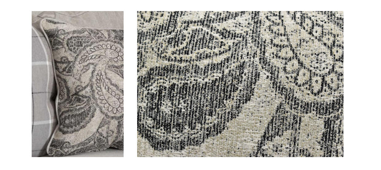
Examples of Bad Material Reference Images.
These images are not usable, they are cropped so the full pattern is not visible
and the lighting is considerably different between the two images.
Special Cases for Material Reference
PILLOWS
When ordering pillows, there are a few more requirements for material reference imagery.
Images need to include a close up, full view of the fabric so that the pattern can be accurately made.
Pillows will often be made from a smaller section of a larger stretch of fabric. In the case where the fabric is patterned (floral, geometric, imagery of any kind) we cannot make the material if the full, repeatable pattern is not visible in reference imagery.
If you find a better image of the fabric in question, feel free to attach it even if the image is not of a pillow.
On occasion, the pattern on throw pillows can also be found on other products in the same family, most commonly an armchair. If possible, uploading an image of the armchair and labeling it as the pillow pattern is also quite beneficial.
Pillow orders should exclude photos of the pillow that show it placed on a product if possible
These images usually show a full space or a larger product, making the pillow very small in the final image. These images are usually unusable.
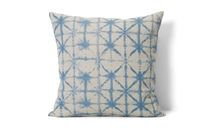
Example of an acceptable reference image for a pillow
WALL ART
Framed wall art or wall art that is generally a rectangular image should always have a clear, high resolution image as reference. The following requirements apply for a high quality final material:
At least 1000x1000px in overall resolution
Angle should be straight-on. Tilted images can result in a skewed result.
.png)
Example of an ideal reference image for wall art
RUGS
Most rug 3D models and materials are automatically generated internally by a script, based on the provided reference image. Rugs only require one reference image. Since rug materials are generated directly from the provided reference image, you should never provide the same reference image for two different rug materials. This would result in two identical materials. Rug material requirements are listed below:
Angle must be top-down
Background must be white
Rug should be as straight as possible. Deviation from perfectly straight can result in edge clipping or added white space on the sides.
Example of a high quality reference image for a rug

Pivots
All orders with reference imagery may also include a Product Pivot Reference Image (PPRI). This image is used by the studios to know where they should place the 3D Model’s pivot in relation to the geometry. You will only need to provide a PPRI if your product requires a non-standard pivot location. Additionally, material orders that do not include products/geometry do not need a PPRI.
You can find all available PPRI files HERE
Pivots are used in 3D Cloud when moving or placing products
Objects will rotate around their specified pivot
Objects will load with their pivot at “World Center”, meaning at the center of the 3D grid in 3D Cloud.
If a sofa’s pivot was in the center of its mass, the sofa would load into 3DCloud halfway through the floor.
|
|
|---|---|
Example Product Pivot Reference Images (PPRI) | |
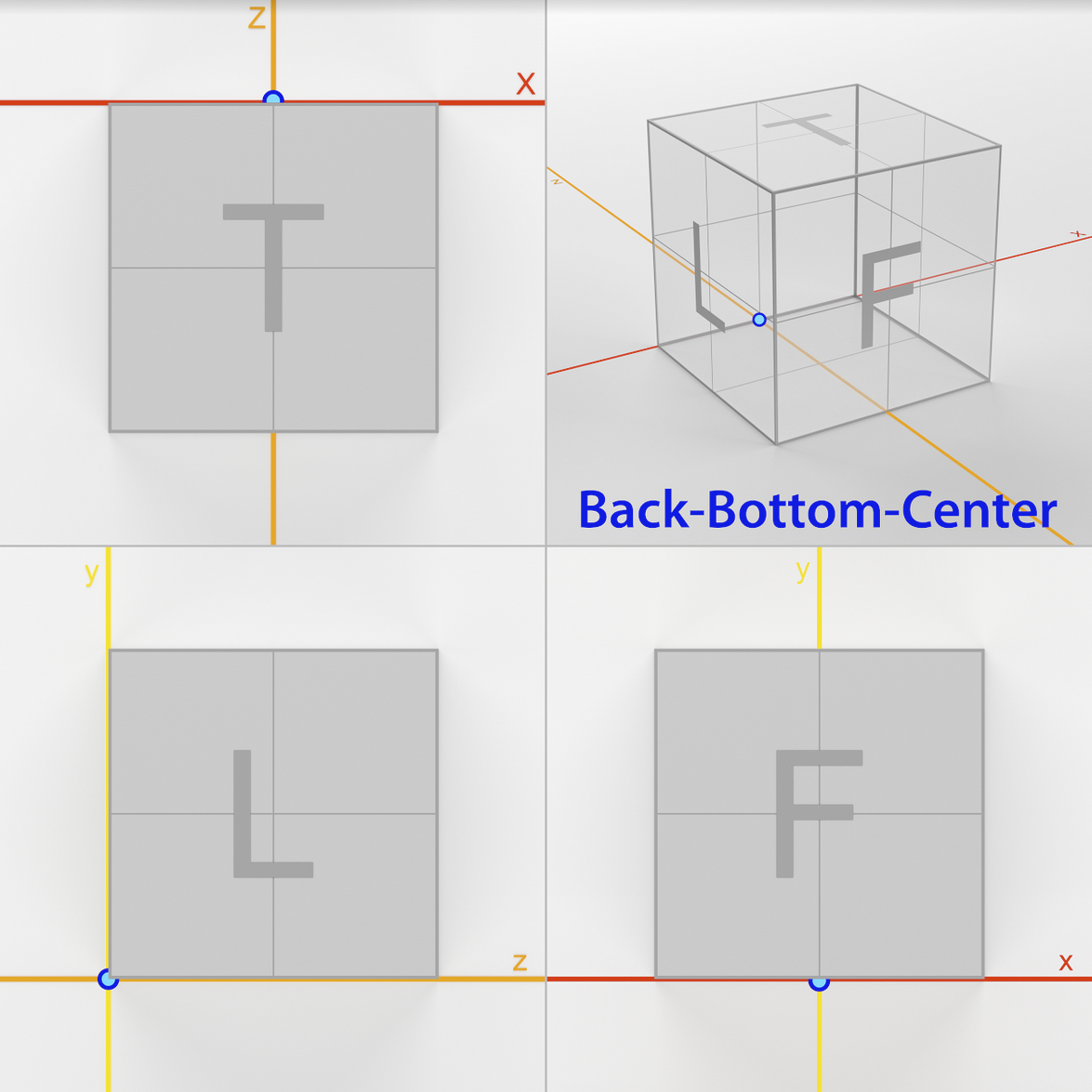
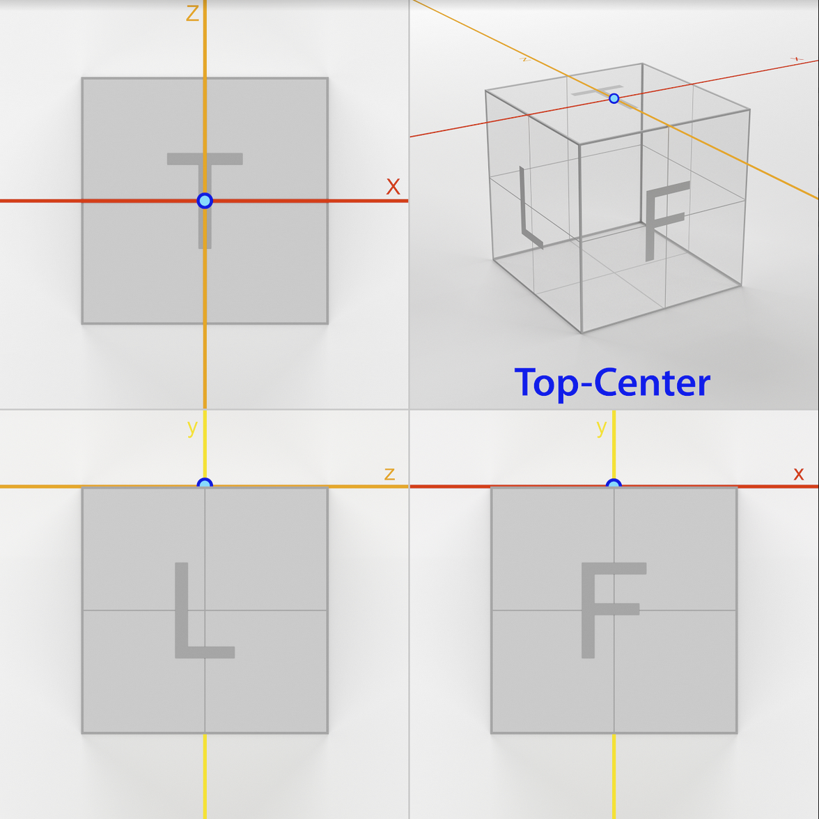


Order Breakdown Process (“Data Discovery”)
When an Order Form is received, it is reviewed for completeness by a 3D Cloud Account Director or Project Manager (or Client lead, if self-service) and is ready for the Order Breakdown process, also called Data Discovery. During this process, 3D Cloud Data/Business Analysts review each SKU in the order sheet and separate them into appropriate Product Batches (virtual products) and Asset Batches (Meshes, Materials) for ordering from 3D Studios.
The Order Breakdown page has two different view options of the same information which can be toggled with the “View As” toggle in the top center of the page.
View as Batches
In this view, the “cards” of Products or Assets in Column 3 can be dragged one-by-one to Batches created in Column 2. This process can be time-consuming if large SKU counts are being processed, which is why the View as List option was created.
Column 1 (Left): SKU List
Column 2: Product Batches
Column 3: Product / Assets List
Column 4: Shows details, references, etc. for the products/assets
Bottom right: SKU Details
.png)
View 1: Order Breakdown Page (Products, View as Batches)
View as List
The Order Breakdown List View displays the SKUs, Batches, Products and Assets information in a spreadsheet view.
.png)
View 2: Order Breakdown Page (Products, View as List)
The spreadsheet colums are as follows:
Column 1: Row Index number. Clicking this row will bring up the right-hand details panel for the item in that row.
Column 2: Bulk Edit Checkboxes. Clicking the top header checkbox, or multiple row checkboxes displays a blue Bulk Edit button to perform a shared edit for multiple rows.
.png)
Bulk Edit Window
Column 3: Batch Color Indicator showing if the item has been assigned to a batch. Yellow = Not assigned, Green = Assigned
Column 4: Batch Name(s)
Column 5: Product ID
Column 6: Thumbnail Image (URL) Thumbnail preview is displayed here when a thubmnail is assigned for the row SKU/asset.
Column 7: SKUs
Column 8: Name (of product or asset)
Column 9: Type (UV2, Game Art)
Column 10: Family
Column 11: Dimensions
Column 12: Template Product
Column 13: Mesh Name
Column 14: Preview Mesh VCN
Column 15: Mat Name 1
Column 16: Tag
Column 17: Geoless
Column 18: Complex
Column 19: Swappable Mat
Column 20: Data Notes
Column 21: Artist Notes
Product and SKU details are shown in a right panel when the any cell in a row is clicked
Using the List View allows filtered views of the order (i.e. sorting or searching columns), and enables the assignment of Products/Assets to Batches by simply editing the Batch Name column, or by using a spreadsheet upload. This allows for assignment and editing via an external spreadsheet in Excel or Google Sheets (which may be faster for some users), which is then imported into the Order Breakdown page.
Steps to Use an External Sheet for Order Breakdown
Before editing the order information using an external sheet, first use the Export Sheet button to download the current order.
Complete edits on the sheet, and do not change the column order or tabs in the exported sheet.
Import the edited sheet using the Import Sheet button.
Note: Importing a sheet will overwrite all previous batch assigments and data.
.png)
Reference Checks and Product Thumbnail Selection
When all batches are assigned, reference images should also be checked. One image for each product needs to be “tagged” as the representative thumbnail. A bulk image reference and tagging view is available for this purpose. To view the “Bulk Tag Reference Images” feature, follow these steps:
In List View mode, click on a row to bring up the right-hand detail panel
Select the “Reference” tab
Click the “Bulk Tag Reference Images” button
Images with a blue outline will appear as reference images throughout the platform (and for 3D artist reference). They can be toggled off by clicking on the image. Toggling an image off means you no longer want that image to be used as a reference for 3D modeling or Visual Inspection.
Click on the green “Thumbnail” button under the image that you want to be the primary thumbnail for use in client applications.
Additional tags are available for Master Mesh Reference (best image to use as reference for geometry in 3D modeling) and Master Material Reference (best image for matching color, bumpiness, etc). For each product, it is helpful, but not mandatory to select the respective button under the best image for both of these. Once your tagging is complete, click the “Save and Close” button on the Bulk Tag Reference Images modal window.
Additional tags are available to indicate whether the image is Back (B), Front (F), Left (L), Right (R), or Top (T)
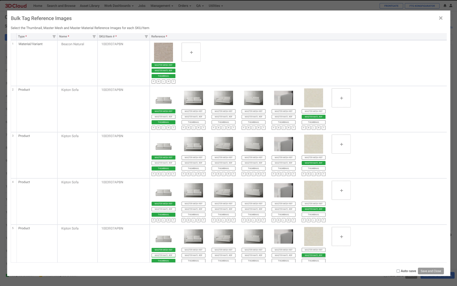
Bulk Tag Reference Images Screen
Note: Once an Order Breakdown has been submitted for 3D Review, thumbnails cannot be (re)tagged again.
Submit for 3D Review
Once the Order Breakdown has been processed and all information added, batches are assigned and thumbnails have been selected, you are now ready to submit the Order to the next step. This is achieved by clicking the blue “Submit for 3D Review” button in the lower right corner.

Upon submittal of the Order Breakdown page:
SKUs in Product Batches are assigned an unique Product ID (PID) for each SKU in the batch.
Asset Batches tell the system to create a unique asset ID, also called a Virtual Commerce Number (VCN). Meshes are assigned a “vcn-mesh-*” ID and materials are assigned a “vcn-mat-*” ID.
The 3D Cloud 3D Lead is notified that the order is ready for review and 3D asset ordering. (FEATURE PENDING)
Order Overview
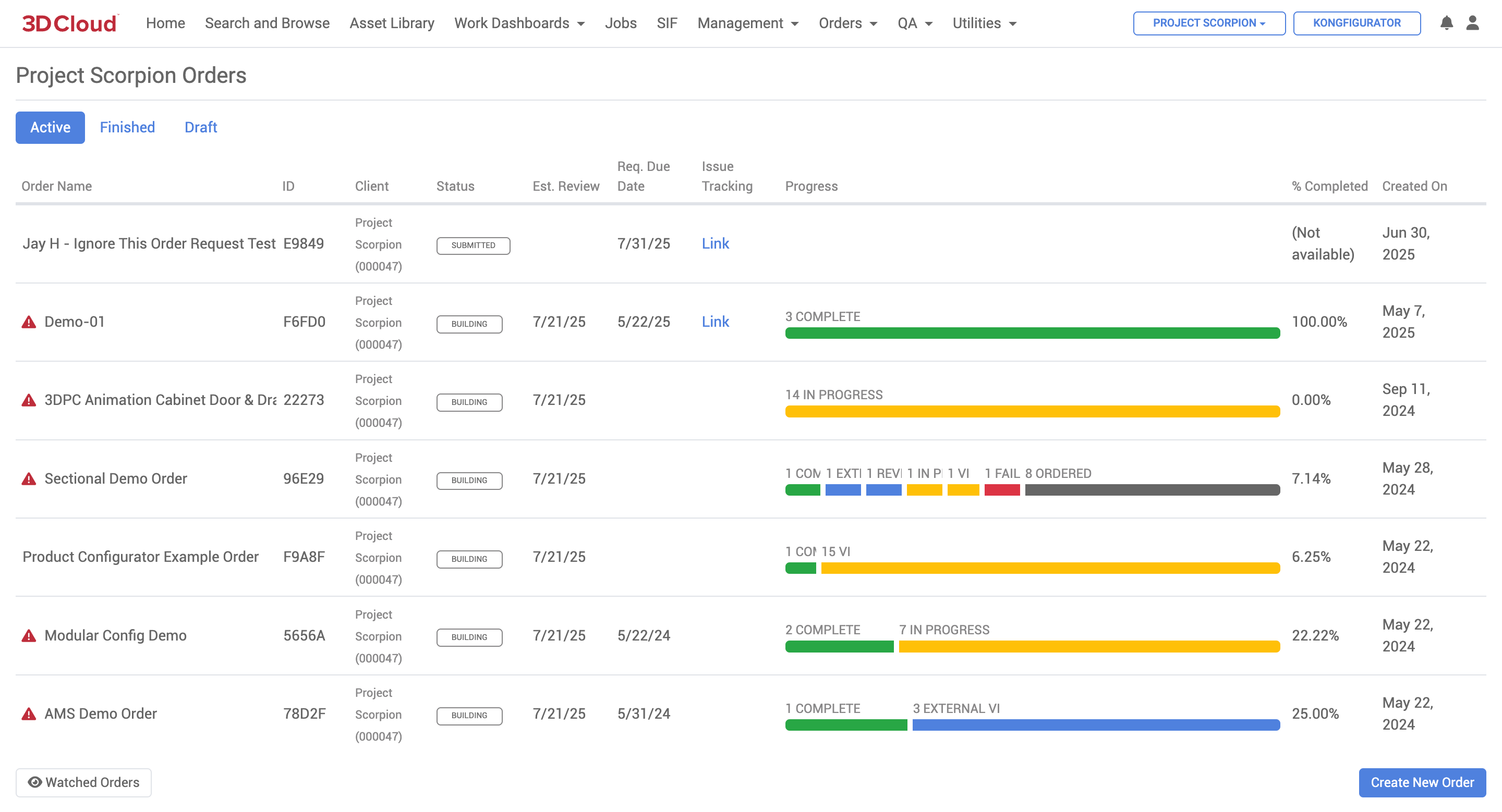
Order Overview
The Order Overview page can be accessed via Utilities → Order Overview. The orders displayed are limited to the current client. All Active, Finished and Draft orders are listed most recent first, with key information such as Order ID, Client, Status, Estimated Review Date, Required Due Date, Jira Tracking Link, Created Date and Progress bar displayed.
Clicking on the Order Name (or in the Order row) will display:
Order Breakdown view (if in Active, Submitted state),
Order Detail Page (if in Active or Finished, Building state), or
Order Form (if in Draft state)
Orders that are at risk of missing their due date are marked with an exclamation icon.
Order Manager
This 3D Cloud AMS Order Manager allows administrator-level users to view orders on a global level. There are search filters and sort controls that expand the scope of the Orders displayed to all Clients and Statuses.
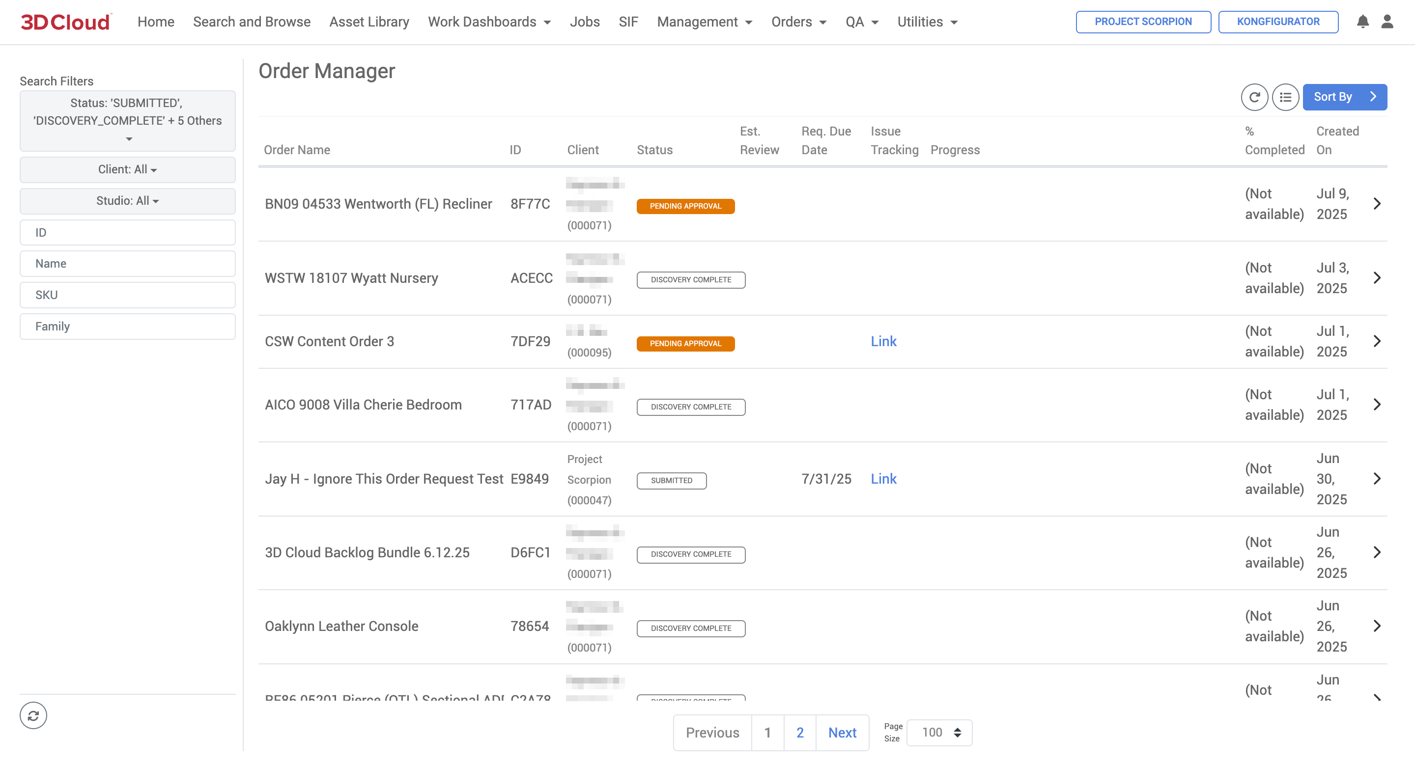
Order Manager
SOW
Once the Order Breakdown is complete, the Order proceeds to a Statement of Work (SOW), which includes all of the Batches defined in the Order Breakdown.
The Order name is copied to the SOW name.
The Work Order number from the Order Approval page is populated on the SOW.
The Reviewer/Approver and Data/BA user email addresses are populated in the Stakeholders section.
Each Batch from the Order Breakdown sheet is translated into an SOW Group number on the SOW.
The SOW (Statement of Work) section tracks
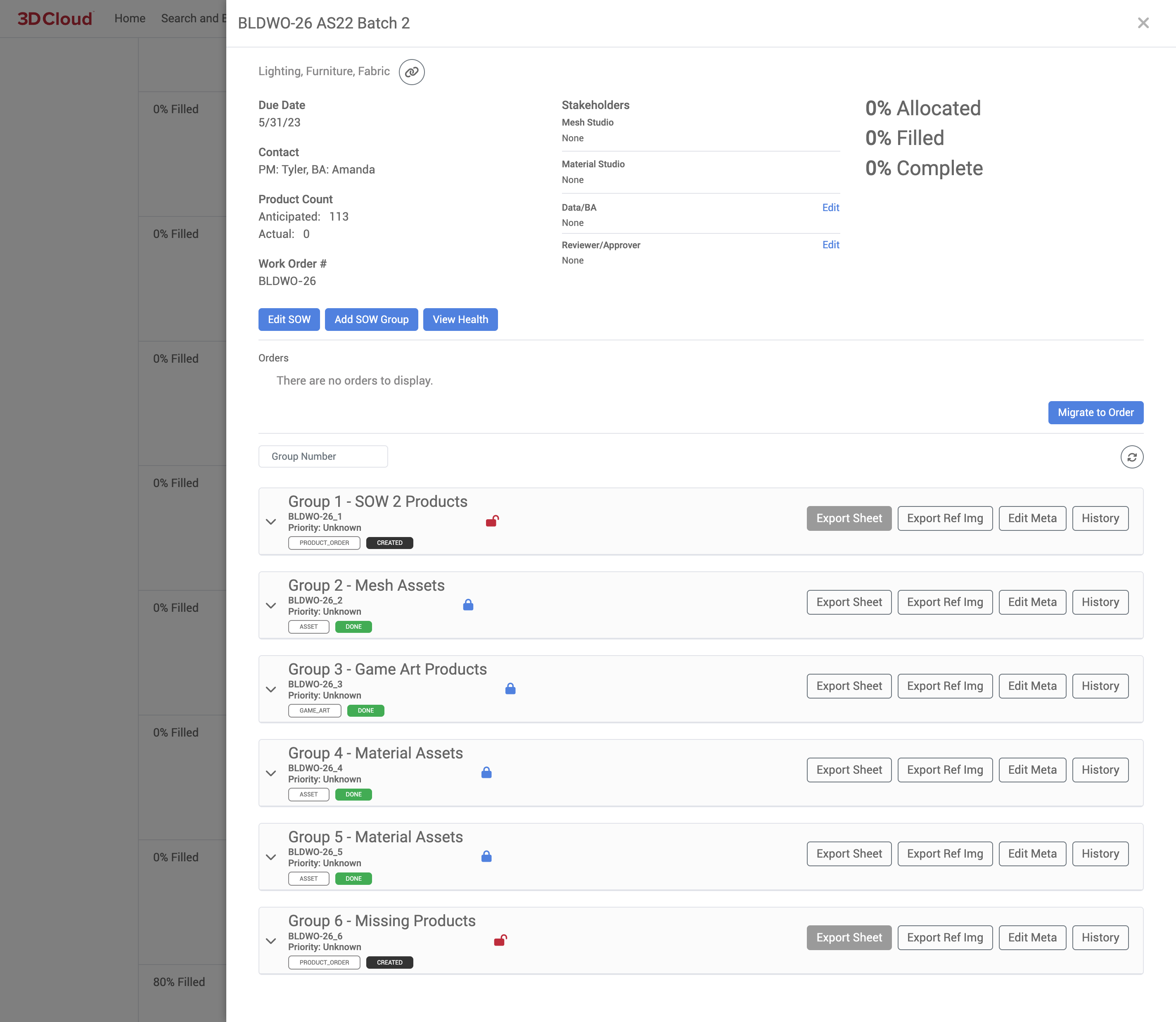
Example: SOW with SOW Groups
SOW Group Manager
The 3D Cloud AMS SOW Group Manager tool (from the main menu, Management → SOW Group Manager) is used to rank and prioritize work on a global level across clients. Each SOW Group can be moved up or down in priority on this view. SOW Groups in REQUESTED, REJECTED, and ASSIGNED status will appear in this view. This allows our 3D Studio Manager to control the priorities of work across our studio network.
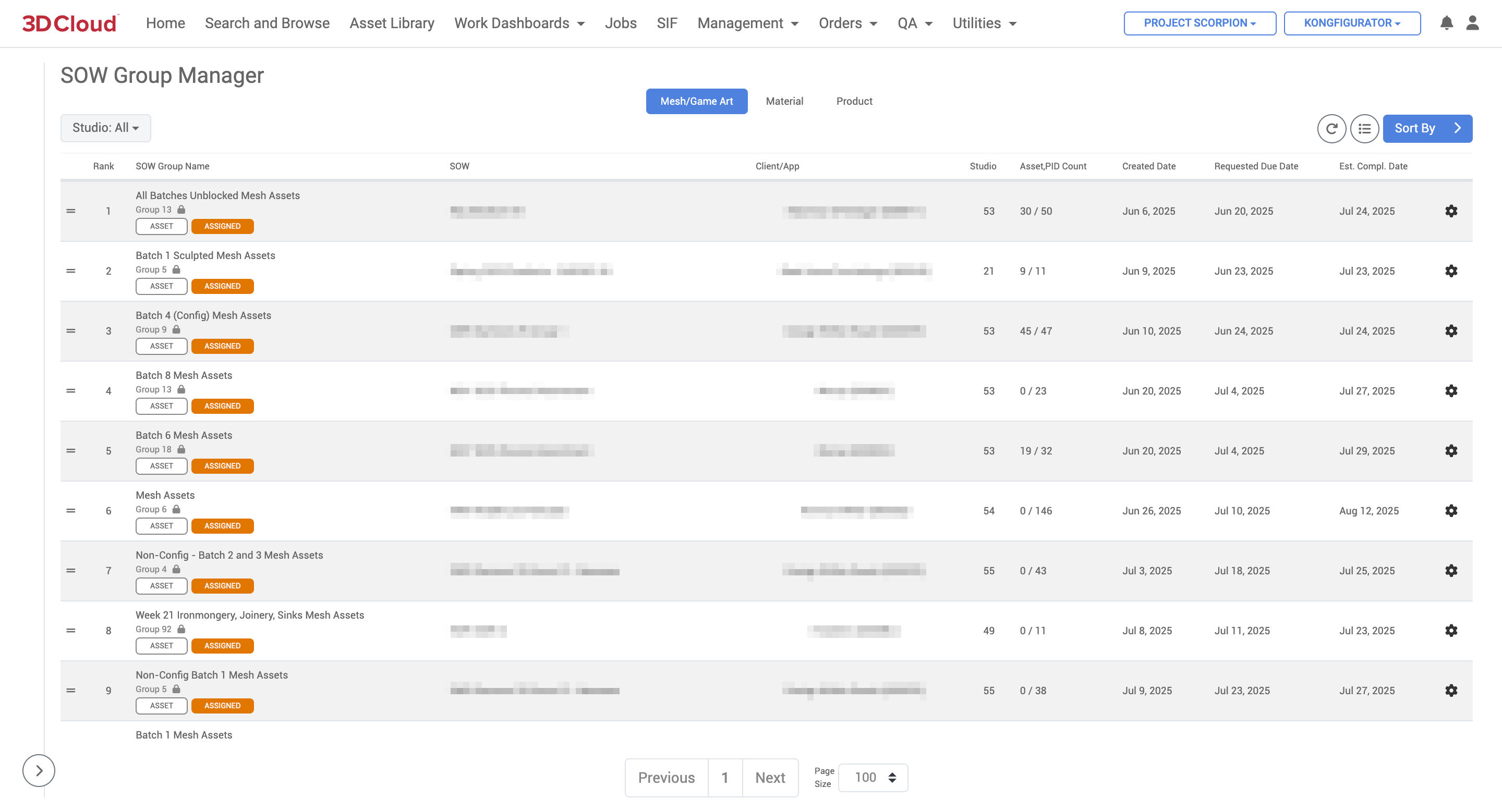
SOW Group Manager
SOW Group Ranking
To re-rank SOW Groups, grab the horizontal bars (“=” icon) on the left-hand side of a row and drag it to a new position in the table. The top of the list has highest priority. After re-ordering group ranks, the estimated completion dates will refresh after a few seconds.
SOW Group ranks are independently ranked within the Mesh/Game Art, Material, and Product group types.
It is also possible to specify a particular rank (vs. dragging) using the context menu on the right-hand side of a row (the gear icon):
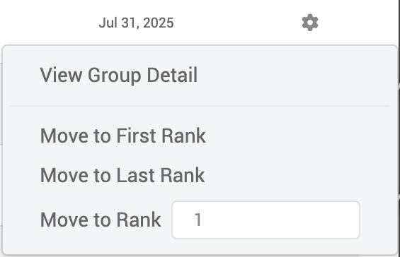
SOW Group Detail
To view the detail of a particular SOW Group, such as the assets or products assigned to a group, click the View Group Detail button under the context menu of a table row.
Estimated Completion Dates
The estimated completion dates of SOW Groups are cumulative based on rankings. So, updating the rank of a group will affect the completion date of all lesser-ranked groups. The basic formula for completion days is the sum of:
(Total Assets or Products - Completed Assets or Products) / Throughput
for each group in the ranking list. When calculating actual dates based on estimated completion days, Sundays are excluded.
Throughputs
Estimated completion dates of SOW Groups are calculated using throughput values which define approximately how long a particular asset/product type takes to build. These throughput values can be edited globally via Global Settings, available at the Settings → Global Settings menu. Relevant keys for SOW Group Manager are GAMEART_THROUGHPUT, MATERIAL_THROUGHPUT, MESH_THROUGHPUT, and PRODUCT_THROUGHPUT.
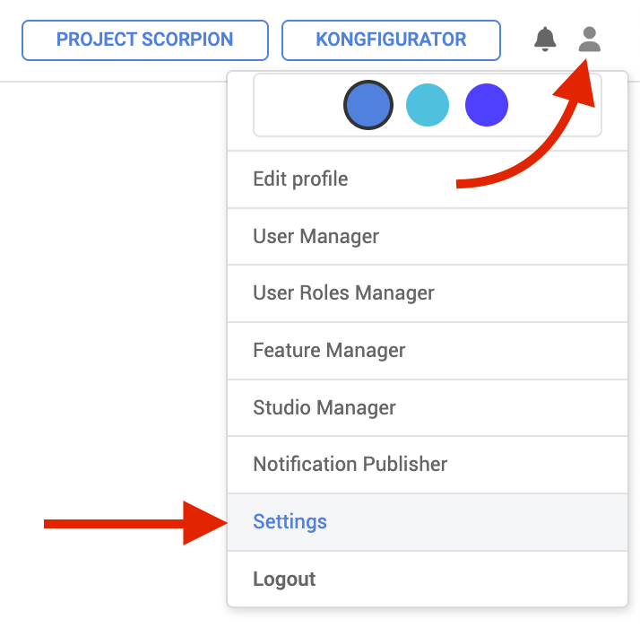
.png)
Throughput values can also be defined on a studio level. SOW Groups assigned to a particular studio will use that studio’s throughput settings, and will fall back to global settings if custom values are not found. Studio throughput values can be edited via Studio Manager.
Order/Asset Status
3D Cloud AMS Statuses play a critical role in managing the workflow of assets and products, providing a structured way in the platform to track progress and ensure effective communication throughout the production process.
There are several categories of statuses related to the workflow and management of assets and products that you will encounter within the system. Here’s a summary of the statuses categorized by their context:
1. Order Statuses
DRAFT: Initial status when an order is created.
SUBMITTED: Status after the order is submitted for processing.
IN PROGRESS: Indicates that work is being done on the order.
READY FOR REVIEW: The order is prepared for client review.
COMPLETED: All content related to the order is finished and ready for client access.
2. Product Statuses
ORDERED: Status when a product is initially ordered.
IN PROGRESS: Indicates that the product is currently being worked on.
READY FOR INSPECTION (Internal): The product is finished and awaiting internal review.
EXTERNAL VI (Visual Inspection): The product is ready for client visual inspection.
PASS/FAIL: Indicates the outcome of the inspection, leading to either completion or a need for review.
3. Asset Statuses
CREATED: Initial status when an asset group is created.
REQUESTED: Indicates that the asset group is ready to be sent to the studio.
ASSIGNED: Status when the asset group is assigned to a studio for work.
REJECTED: Indicates that the asset group is not ready due to missing information or issues.
COMPLETED: Signifies that the asset work is finished.
4. SOW (Statement of Work) Group Statuses
CREATED: Status when a SOW group is initially established.
REQUESTED: Indicates readiness for studio assignment.
ASSIGNED: The SOW group has been assigned to a studio.
REJECTED: The group is not ready for processing.
COMPLETED: All tasks within the SOW group are finished.
5. General Workflow Statuses
VI (Visual Inspection): Used to indicate that an asset or product is ready for visual inspection.
Review: A status indicating that a product or asset is under review, often after failing an inspection.
Management and Setting of Statuses
Manual Updates: Many statuses are set manually by team members during various stages of the workflow, such as when an asset is assigned to a studio or when a product is ready for inspection.
Automated Updates: Certain statuses may be updated automatically based on the completion of tasks or through the use of templates during the order breakdown process.
JIRA Integration: The use of JIRA tickets helps in tracking the status of orders and products, linking them to specific tasks and workflows.
Onboarding: Cabinet Catalog
The Onboarding: Cabinet Catalog tool allows the 3D Cloud AMS user to generate, configure, and publish complete cabinet catalogs for use in front-end 3D Cloud applications. For more information on Onboarding Cabinet Catalogs, speak to a 3D Cloud Account Manager.
Key Points
Purpose: The tool enables users to create complete cabinet catalogs using familiar metadata, which can then be published and consumed by frontend apps.
Metadata: Users define the catalog’s name and description.
Species: Allows entry of wood species (e.g., Maple, Oak, Walnut) with SKU, name, and description. This is currently informational only.
Finishes: Users can add finishes (color/material wraps) with details like SKU, name, description, dimensions, manufacturer, and URL. Each finish can have reference files attached.
Door Styles: Logical door objects are created, each with a SKU, name, description, manufacturer, and URL. Door styles can be bulk imported and set as default for the frontend.
Compatibility Matrix: Defines which species and finishes are compatible with each door style. At least one default finish per door style is required for catalog generation.
Product Generation: When generating a catalog, the tool creates products and assemblies based on user input, including mount points, MACs, and steps. Each door style template generates several product variants.
Families: Catalogs are organized into families (Base, Wall, Tall cabinets), each with its own set of attributes and configuration options.
Functional and Procedural Data: Each cabinet entry includes both functional (e.g., SKU, name, dimensions) and procedural (e.g., cabinet type, build style, panel thickness, hardware options) data.
Saving and Storage: Catalogs are saved to cloud storage. There’s a known bug where form data may appear changed after reloading.
Catalog Generation and Validation: The "Generate Catalog" button creates all necessary data for frontend consumption. If the button is disabled, it indicates a validation error or that the catalog must be re-opened.
Editing and Re-opening: Catalogs can be re-opened for editing if needed.
QA
The QA (Quality Assurance) section of the 3D Cloud AMS includes tools used to check 3D assets and product configurators for accuracy and quality.
Visual Inspection (VI)
The Visual Inspection (VI) tool can be accessed at QA → Visual Inspection. “VI” is the process of examining meshes, textures/materials, and products for accuracy to source reference imagery and data specifications. The 3D Cloud AMS provides robust tools to complete this process.
Products can be examined side-by-side with reference images in the Visual Inspection tool.
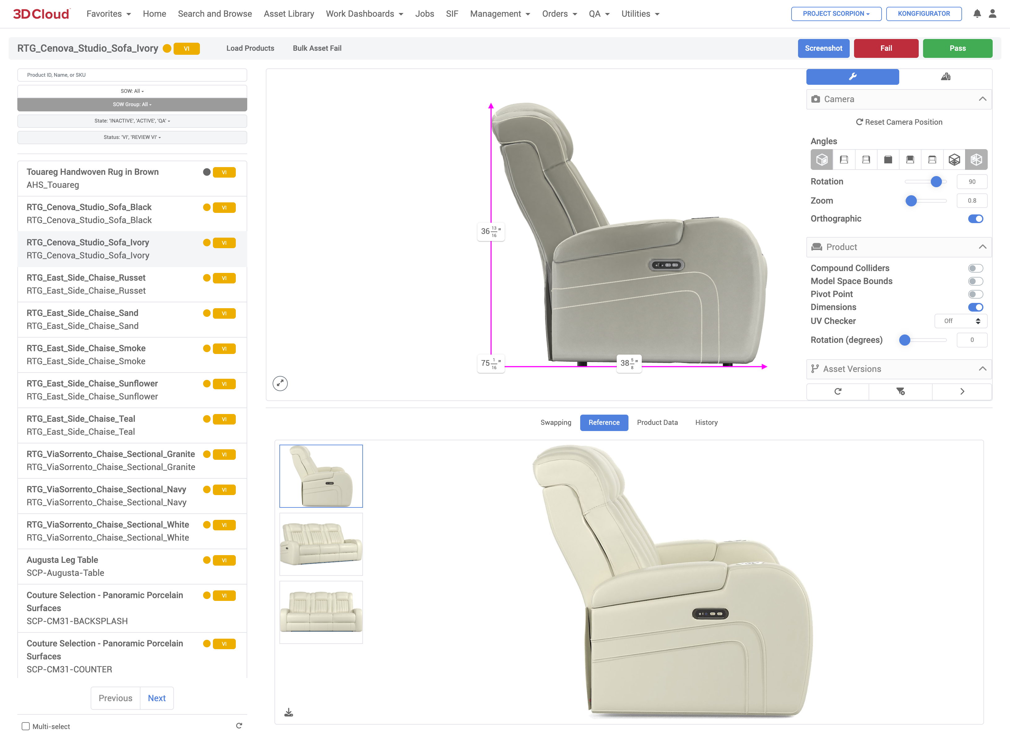
Using this tool, many aspects of assets are checked using visual inspection, including general proportions, shape, product orientation, product details, dimensions, UV Vert Count, Mesh Count, Material count, pivot point placement, UV layouts, etc.
If a product has issues, the "Fail” button is clicked, an appropriate Product Fail Category is selected, and comments are entered. Fail comments are retained in the asset’s history.
If a product has no issues, the “Pass” button is clicked to indicate approval of a product/asset.
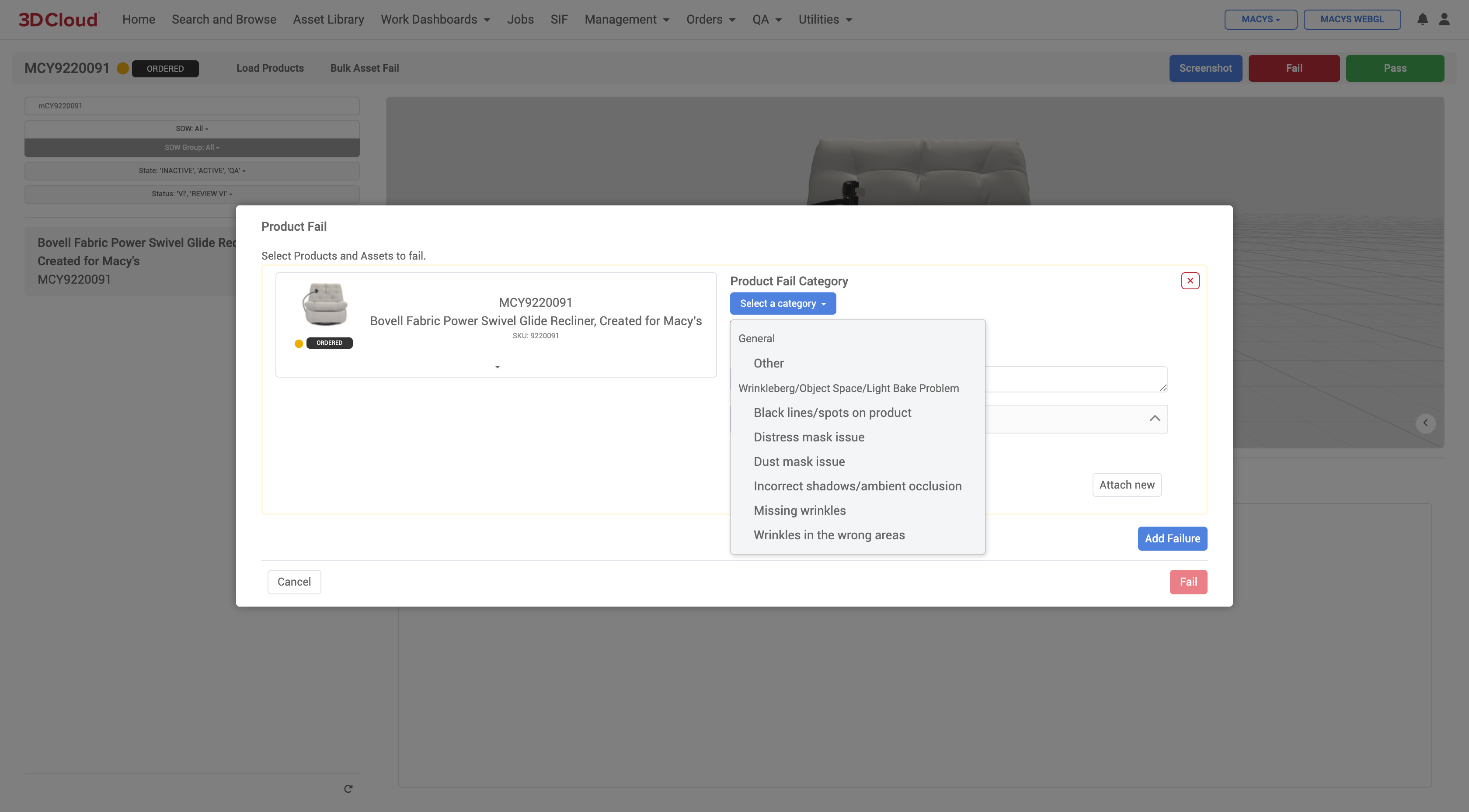
Visual Inspection (VI) Tool Fail Modal Window: Product Fail Category Selection
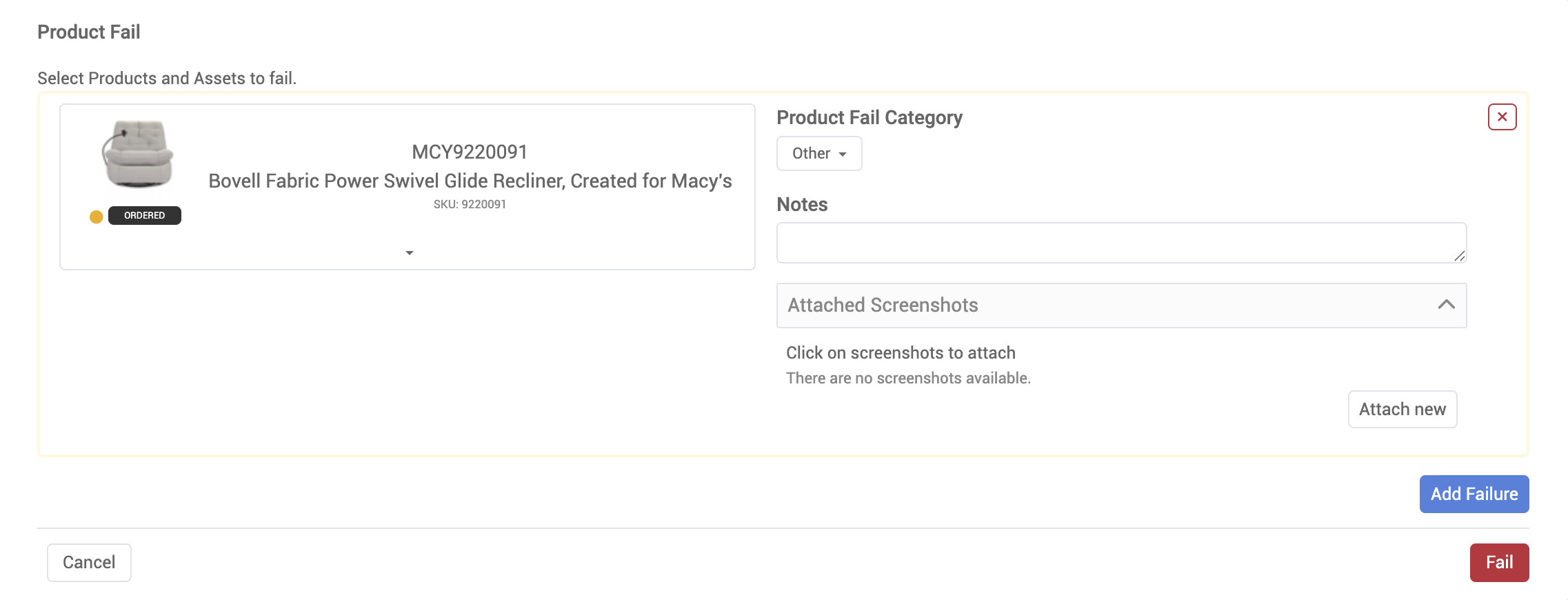
3D Product Configurator Inspection
The 3D Product Configurator Inspection Tool is a powerful visual verification tool that provides QA Analysts the ability to test a Configurator in a view as close to the live site/implemenation as possible while passing or failing each of the configurator’s Steps and Step Options. The assigned author of the configurator can then view the QA states and address each issue, or “fail back” specific geometry and/or materials to the 3D artists.
Watch this short 5 minute video for a general overview of the entire process from start to finish or continue reading for more detailed information and screenshots. Note: This is an older interface but the functionality is the same.
Key Features
QA Role Required: To use the inspection tool, a specific QA role is required, which can be requested from Marxent support or account teams
Publishing to Test/QA: Configurators must be published to the Test environment to appear in the QA state within the inspection tool
Search Filters: Users can search for configurators by ID or name and filter by state (QA, Pending, Needs Reviewed, or Complete)
Pass/Fail Steps: QA users can review each step and step option, choosing to pass or fail items
Workflow
Configurator Author (Data/BA) publishes the configurator to the Test environment.
External QA User loads the configurator in the inspection tool, selecting it via the QA state menu.
QA Process: The configurator is either Passed and marked complete or Failed and sent back as pending for further review.
Step-by-Step Directions
To open the tool go to the QA menu and select the 3D Product Configurator Inspection tool:
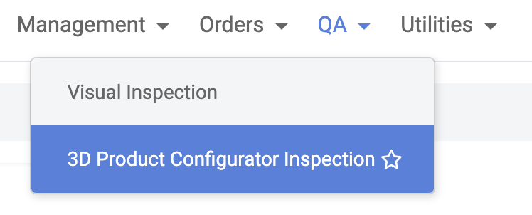
This will open the 3D Product Configurator Inspection Tool with no Configurator selected by default:
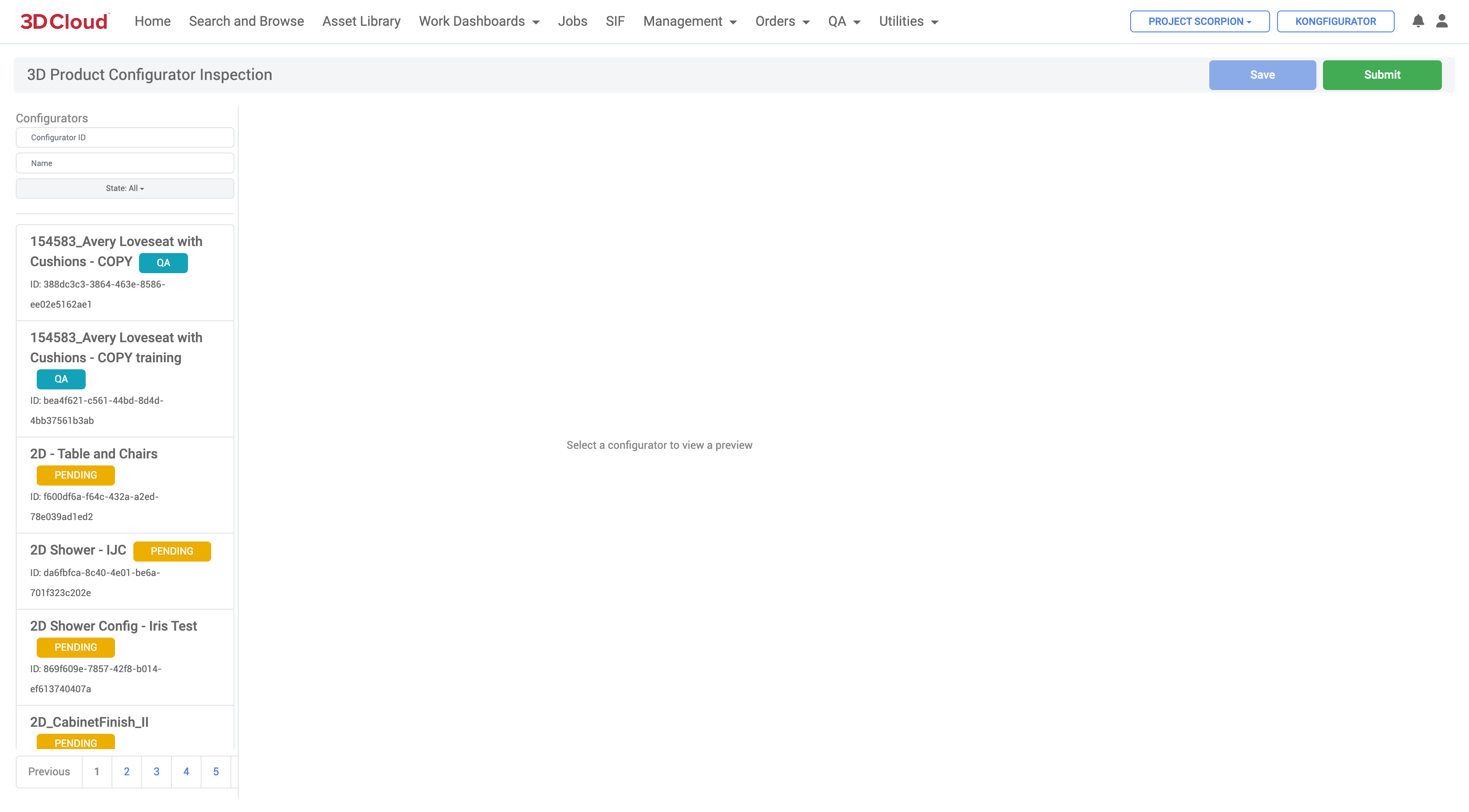
The default list of Configurators promoted to TEST appear as QA state
Search and Filter
| On the left hand side panel, users can search by Configurator ID or Name using the Search Filters above the default list. Select a Configurator to load by clicking on its tile. |
|---|
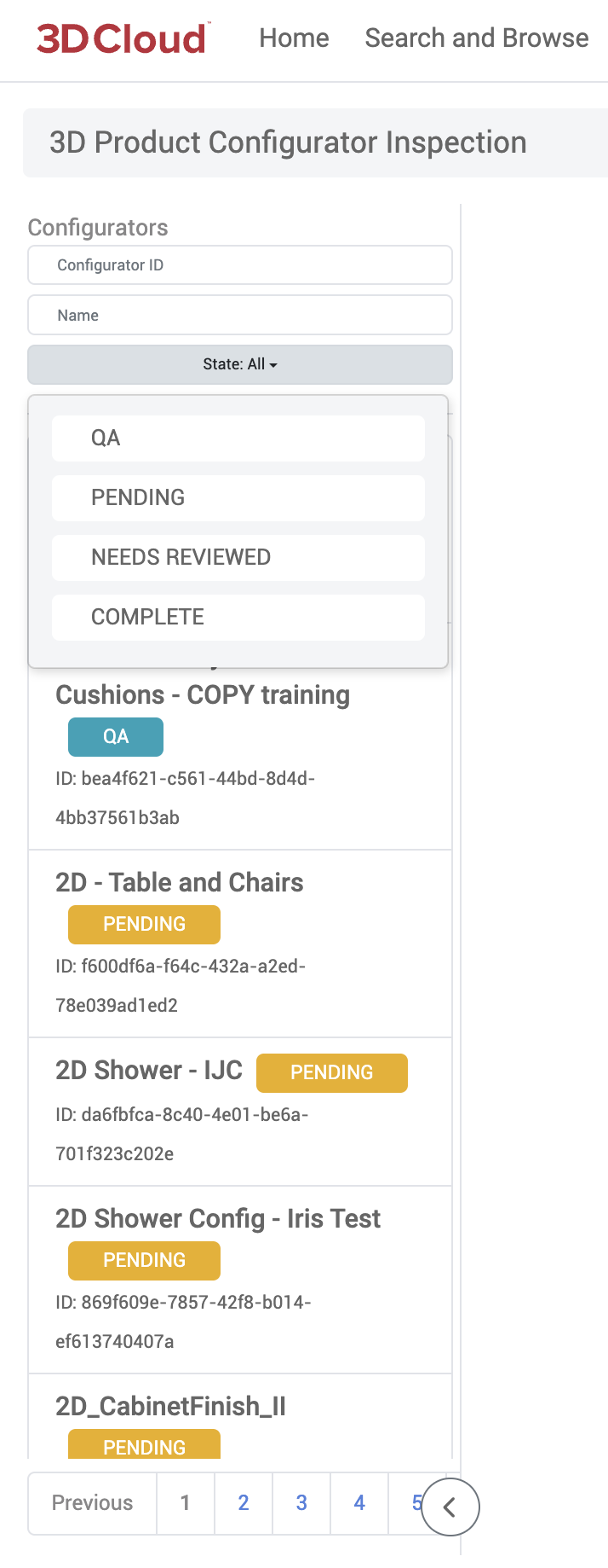
Pass/Fail Steps & Options (External QA)
Users with the QA Role can open a configurator and click to review each Step and Step Option, choosing to Pass or Fail items via the menu which will appear on the right side panel.
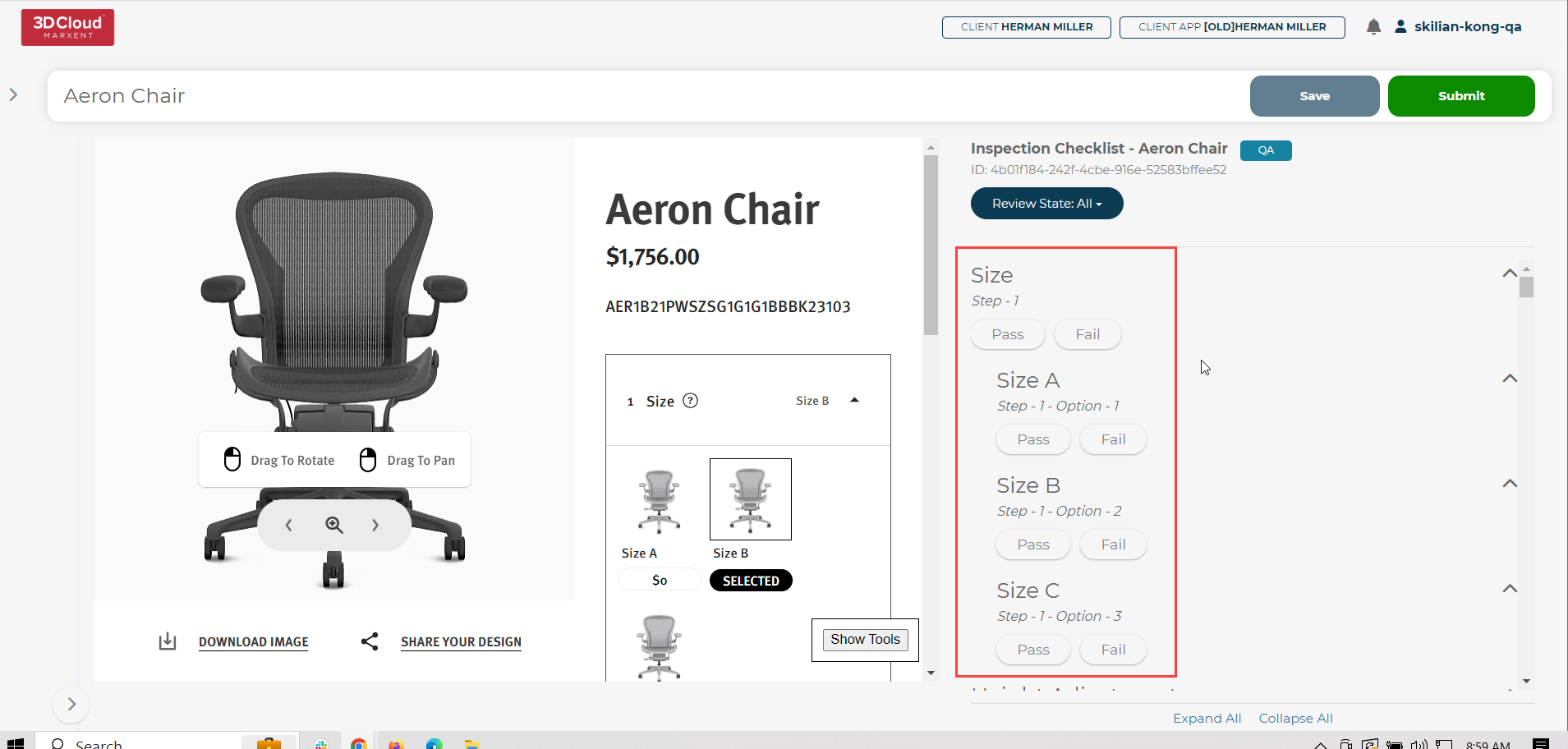
Filter Pass/Fail Steps & Options
Items can be filtered by status via the drop down menu at the top of the right side panel (All, Passed, Failed, Needs Reviewed)
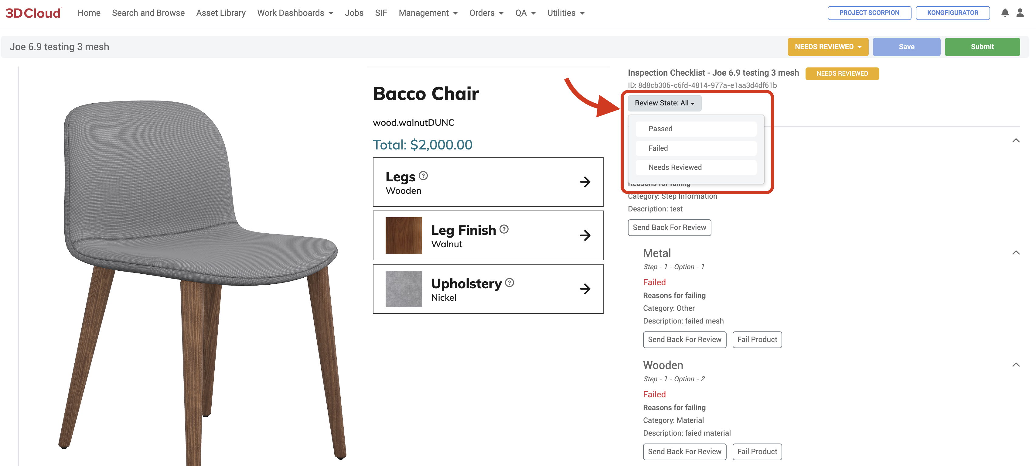
Real-time Step/Option View
Interacting with the configurator on the left will automatically update the items on the right based on the current available steps and options.
Save and Submit
Progress can be saved via the Save button in the top right corner of the page.
Press the Submit button to move the Configurator from QA to PENDING in the default list.
If external QA passes a Configurator, it will be marked as COMPLETE:
If external QA fails a Step/Option, the Configurator will be sent back to the PENDING state upon submission:
Editor Review
Users with the Editor role can review PENDING items submitted and either fix those items and send them back for review or fail the product back to the artists.
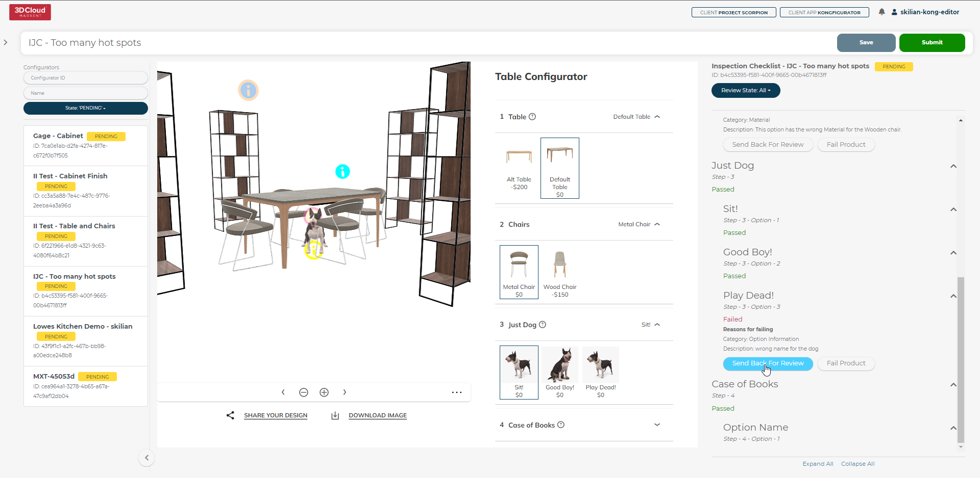
Users can still filter by status using the drop down menu and Save or Submit to the NEEDS REVIEWED State.
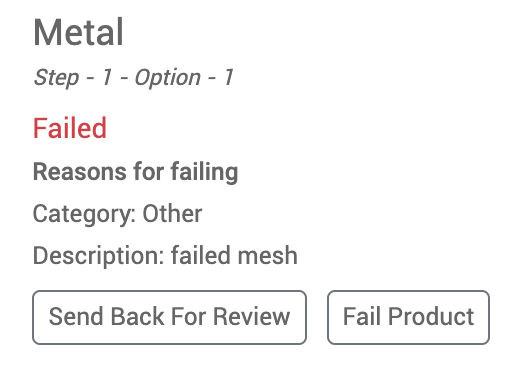
If the user fails the product, a modal will open up allowing for selection of the specific part of the product to be chosen and along with notes failed back to the artist for remediation.
.png)
Utilities
The Utilities section of the 3D Cloud AMS includes tools to manage various aspects of the 3D production process.
AI Image-to-3D (Beta)
Using advanced AI engineering, the 3D Cloud AMS AI Image-to-3D tool is an innovative new feature that can create 3D models (.fbx, .glb, .usdz) and textures from one or more 2D reference images. The resultant model can be assigned to a product in the 3D Cloud system.
Upon entering the AI Image-to-3D section, a gallery of previous generative 3D models is displayed (reference photos are shown for each model).
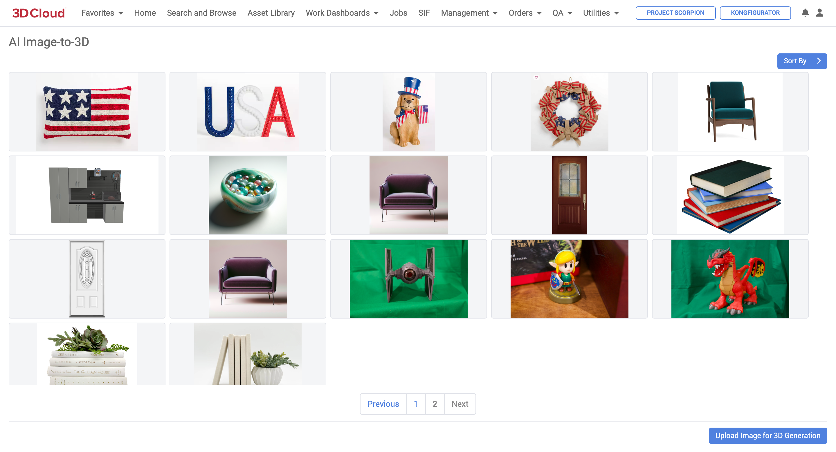
3D Cloud AMS AI Image-to-3D Tool (Gallery)
Note: Currently, this tool works best for staging (“prop”) content where configurability of the asset is not required.
The AI is still in R&D for production furniture modeling.
Required Roles
To use this tool, users must be assigned the “Image-to-3D (3DC)” feature in their permissions.
3D Model Generation: Step-by-Step Instructions
Navigate to Utilities → AI Image-to-3D
Click on the Upload Image for 3D Generation blue button on the lower right
.png)
To upload a new image for 3D generation. You’ll be prompted to Name the image (optional) as well as provide a file (PNG or JPEG).
Select whether you want to use Baked Textures.
Select whether you want to use Symmetry (i.e. the non-visible portions of the image should be symmetrical to the visible portions)
Select whether you want to force the resulting 3D model to specific height, width and length dimensions.
Select whether you want to enforce a pivot point.
Upload the reference image file(s)—up to 5 reference images can be used.
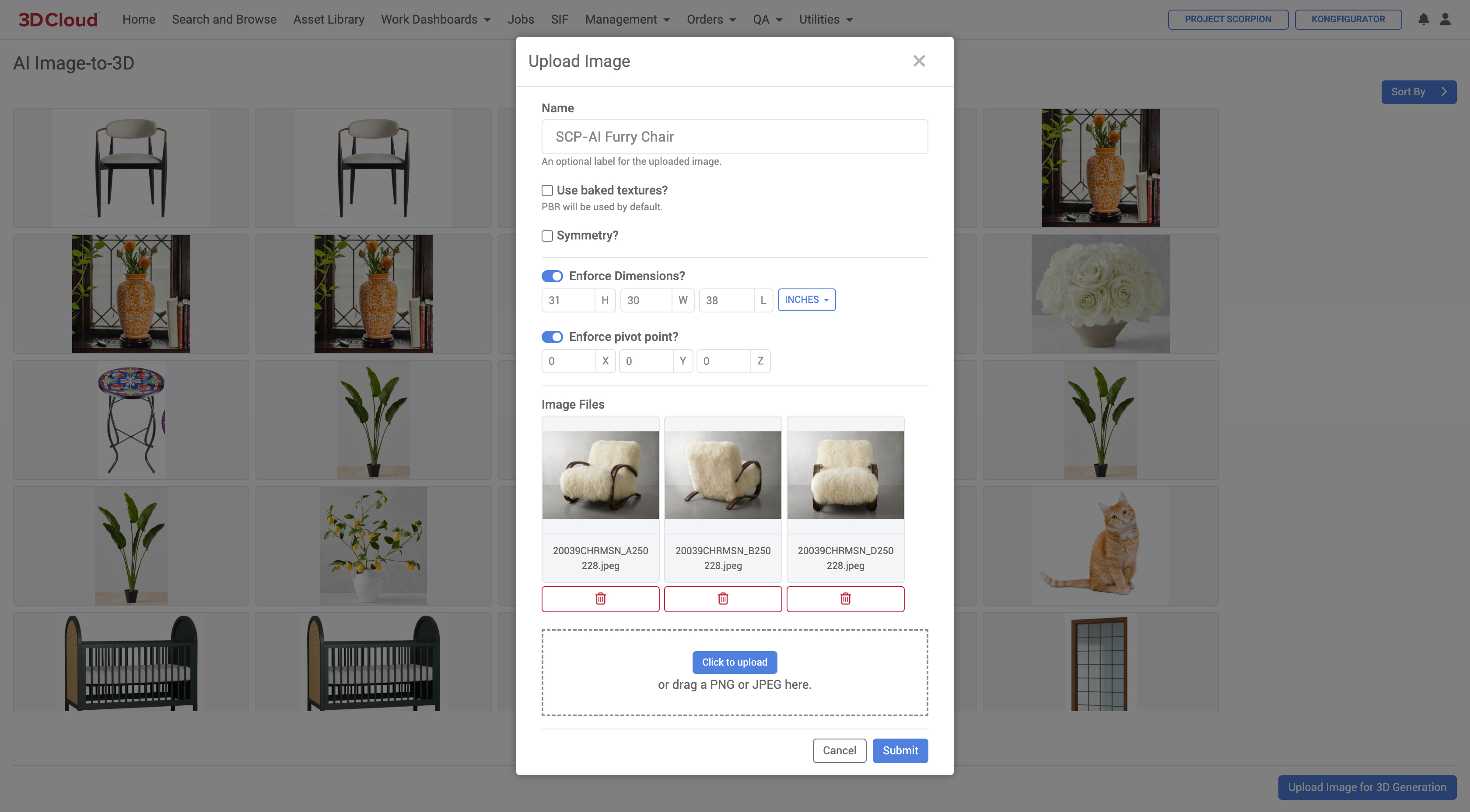
9. Click the Submit button, the resulting 3D model will be generated and displayed in a 3D viewer.
Sample Reference Image | Final AI Image-to-3D Generated 3D Model |
|---|---|
|
|
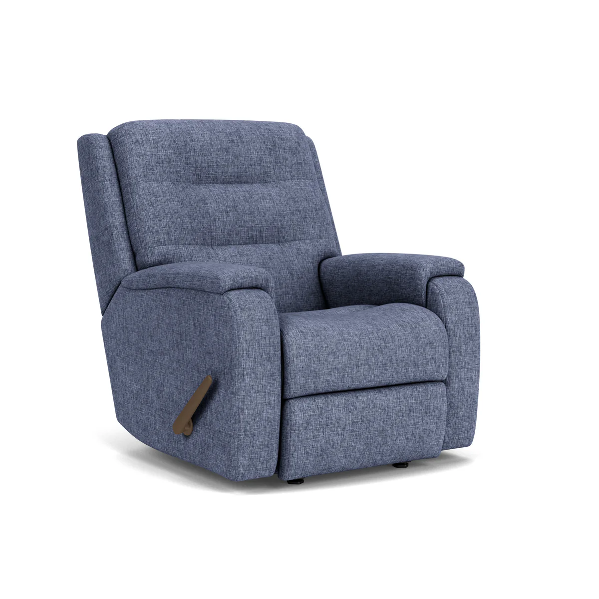
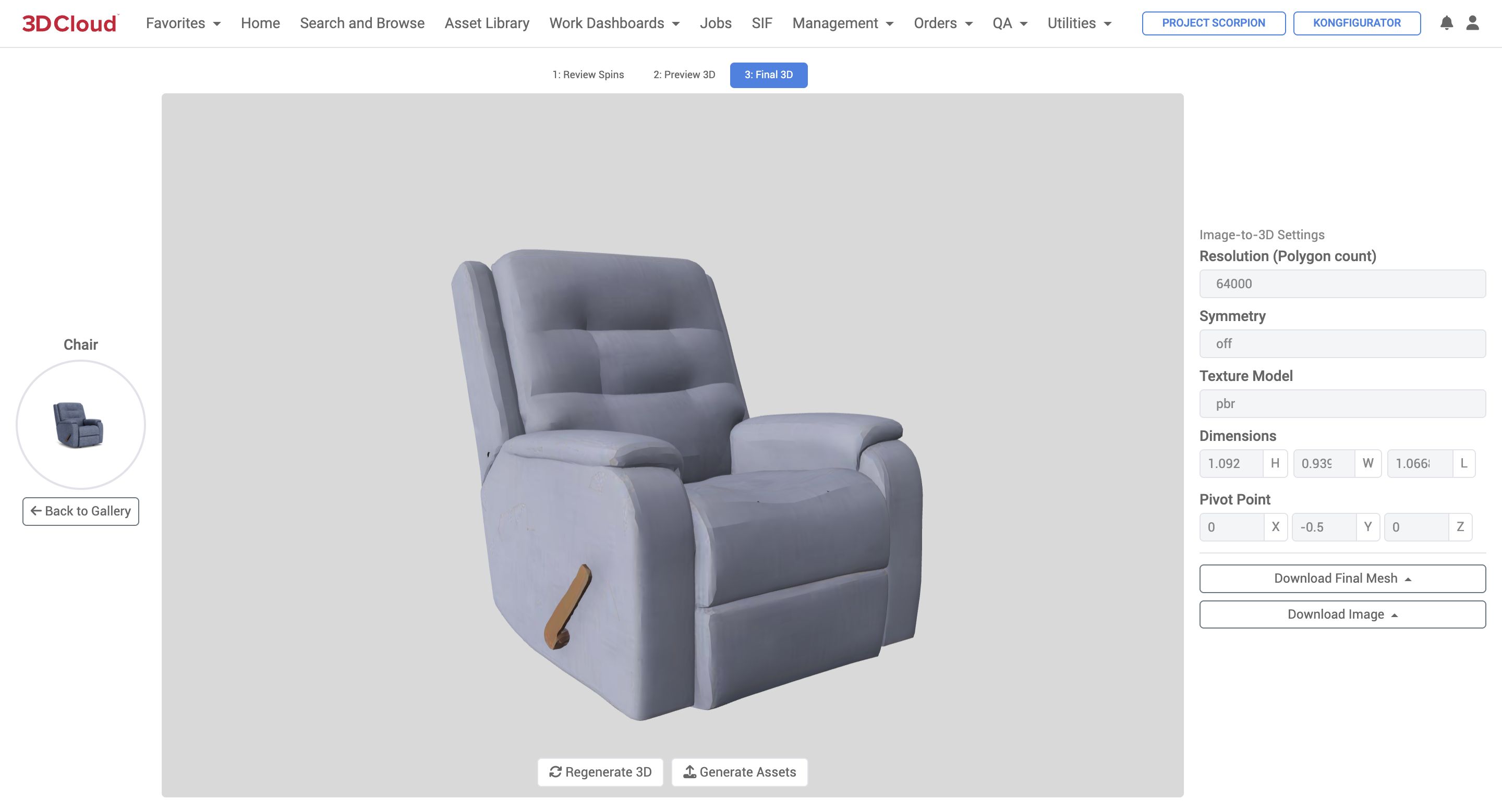
Additional Functions
Regenerate 3D
Click on the “Regenerate 3D” button below the final 3D preview if you are not satisfied with the current result and would like to submit another request to regenerate a new 3D model. The process of (re)generating a model can take in the order of 2-5 minutes depending on the object’s complexity.
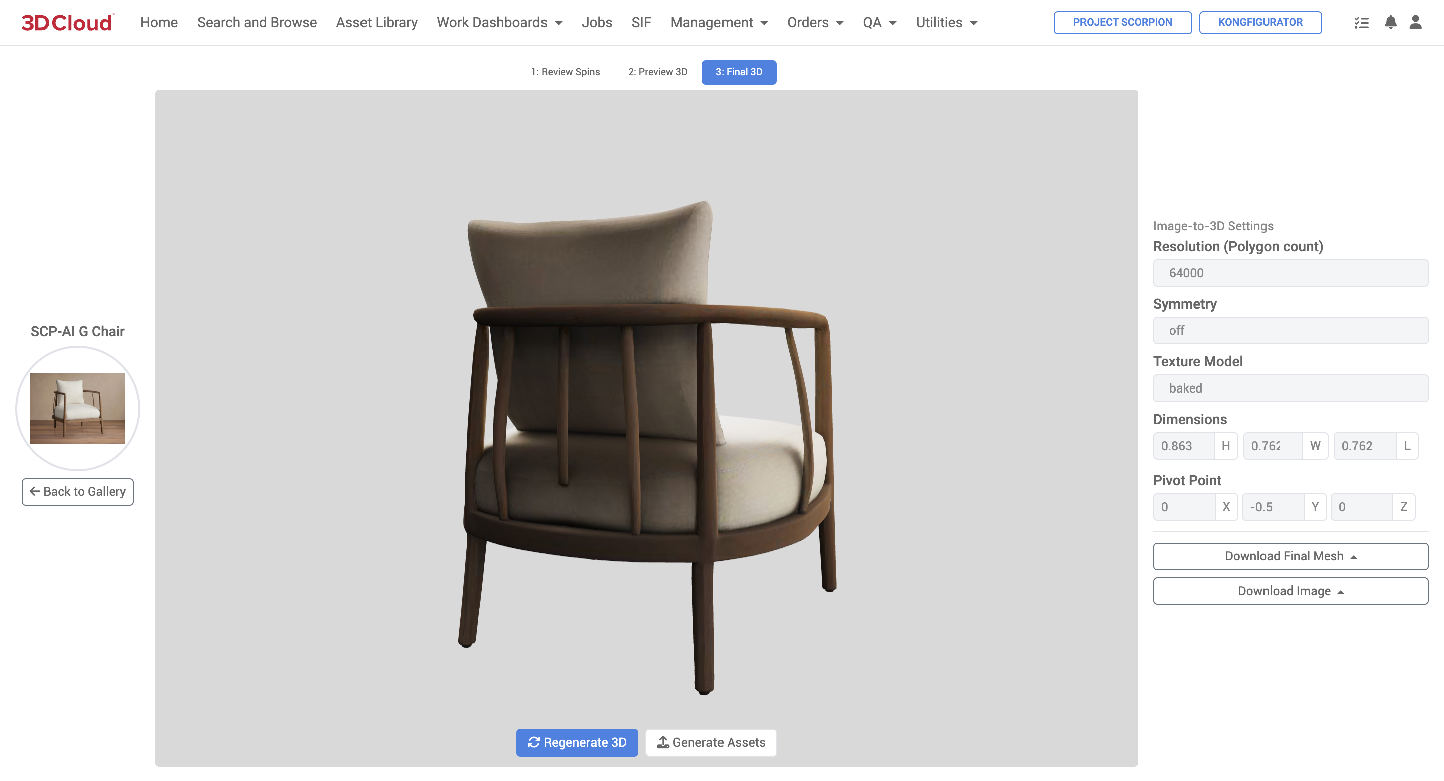
Generate Assets
A virtual product can be created directly from the final generated 3D model.
On the Final 3D preview screen, click the “Generate Assets” button
![]()
Adjust the pre-defined Mesh, Material and Texture names to be created.
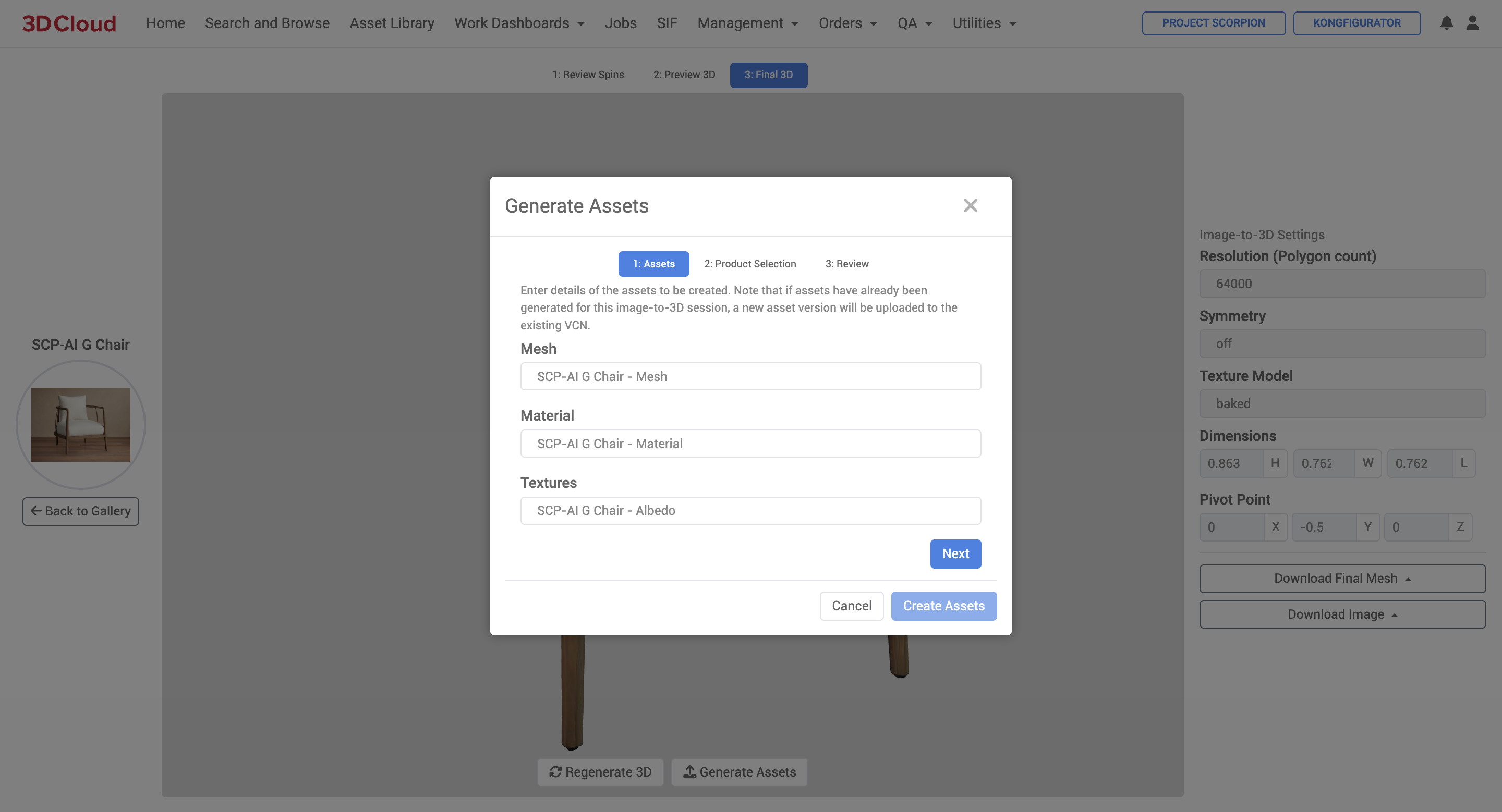
Assign the mesh, material, textures to an existing product by searching for it (by Category, PID, SKU or name containing…) and selecting it, or click the “create a new product” link.
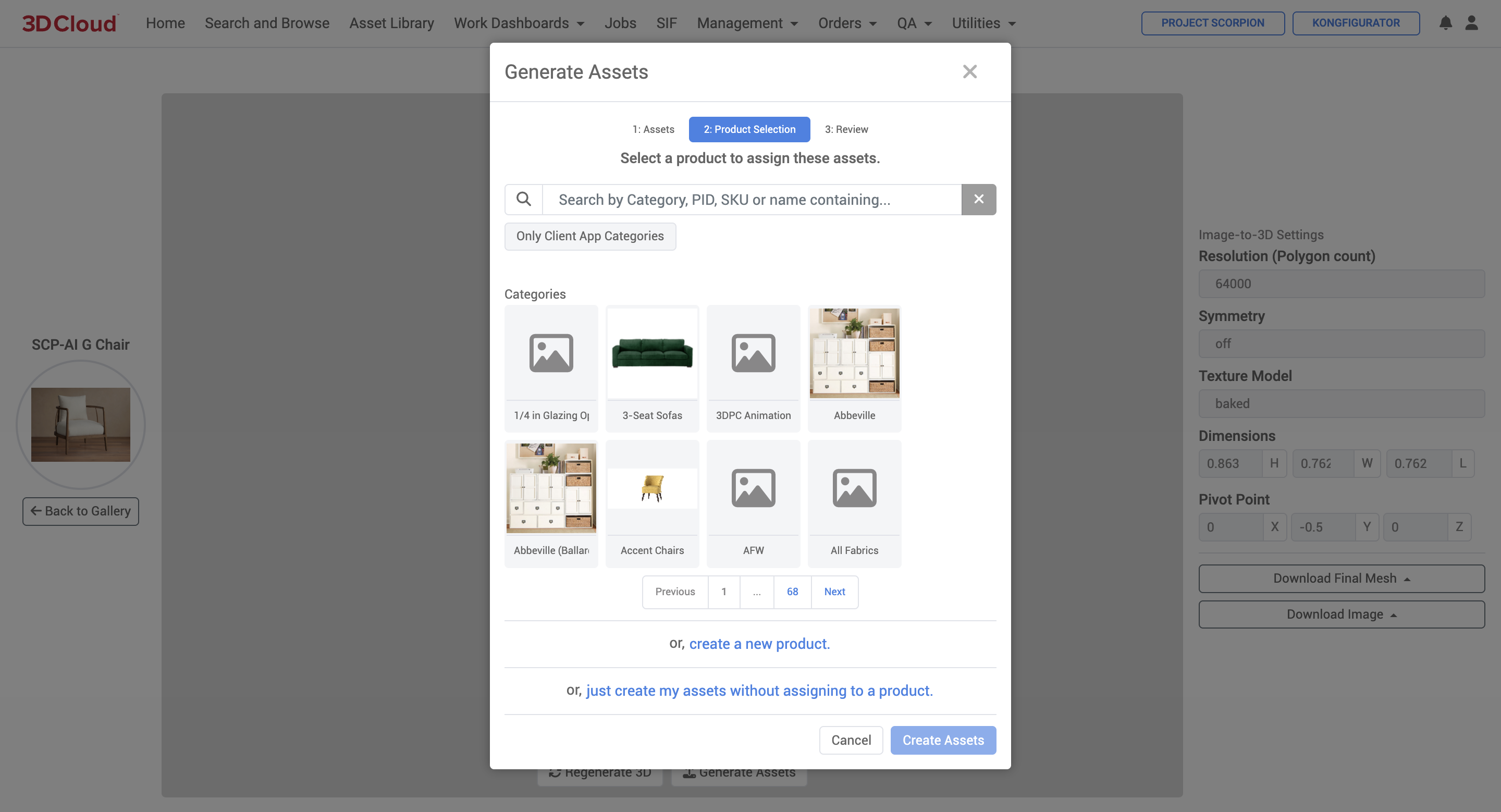
4. If creating a new product, enter the relevant information (Name, SKU/ID, URL, State Compose Surface), Categories and MACs.
Click the “Create Product” button at the bottom when done.
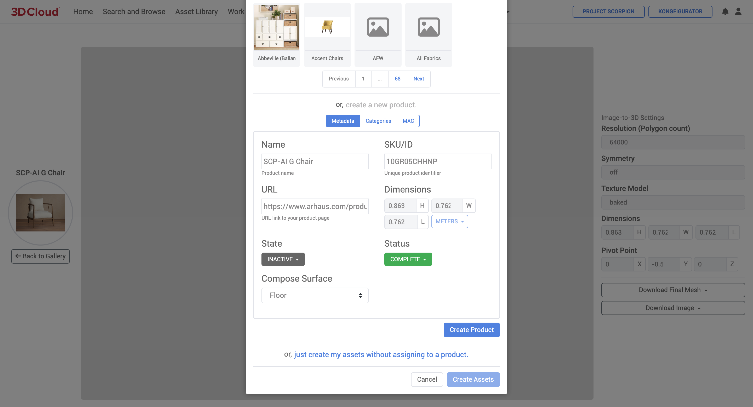
Check the confirmation screen for the name and note the Product ID assigned below the name.
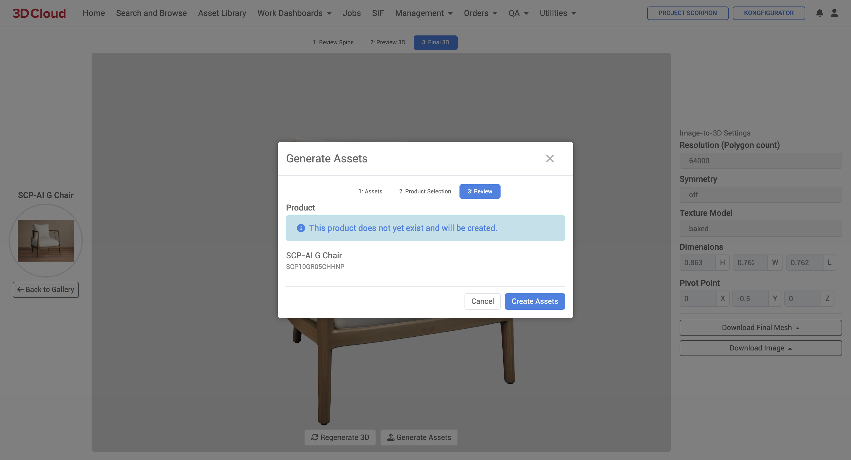
Click the “Are you sure?” button to proceed.
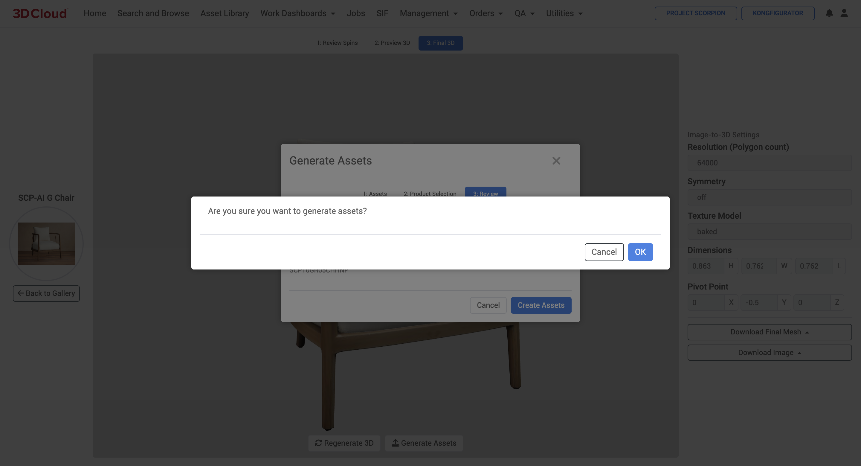
After a minute or so, a summary of the asset vcn files created will appear.
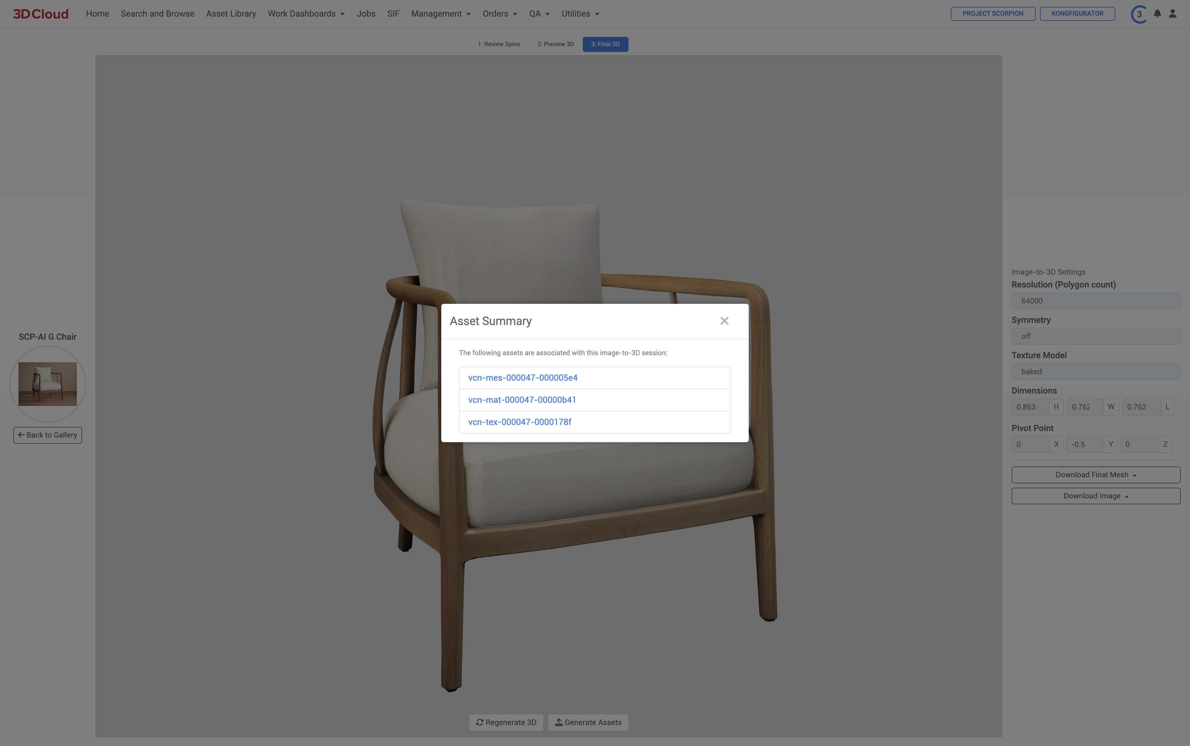
The created/assigned Product page will be displayed and is ready for use.
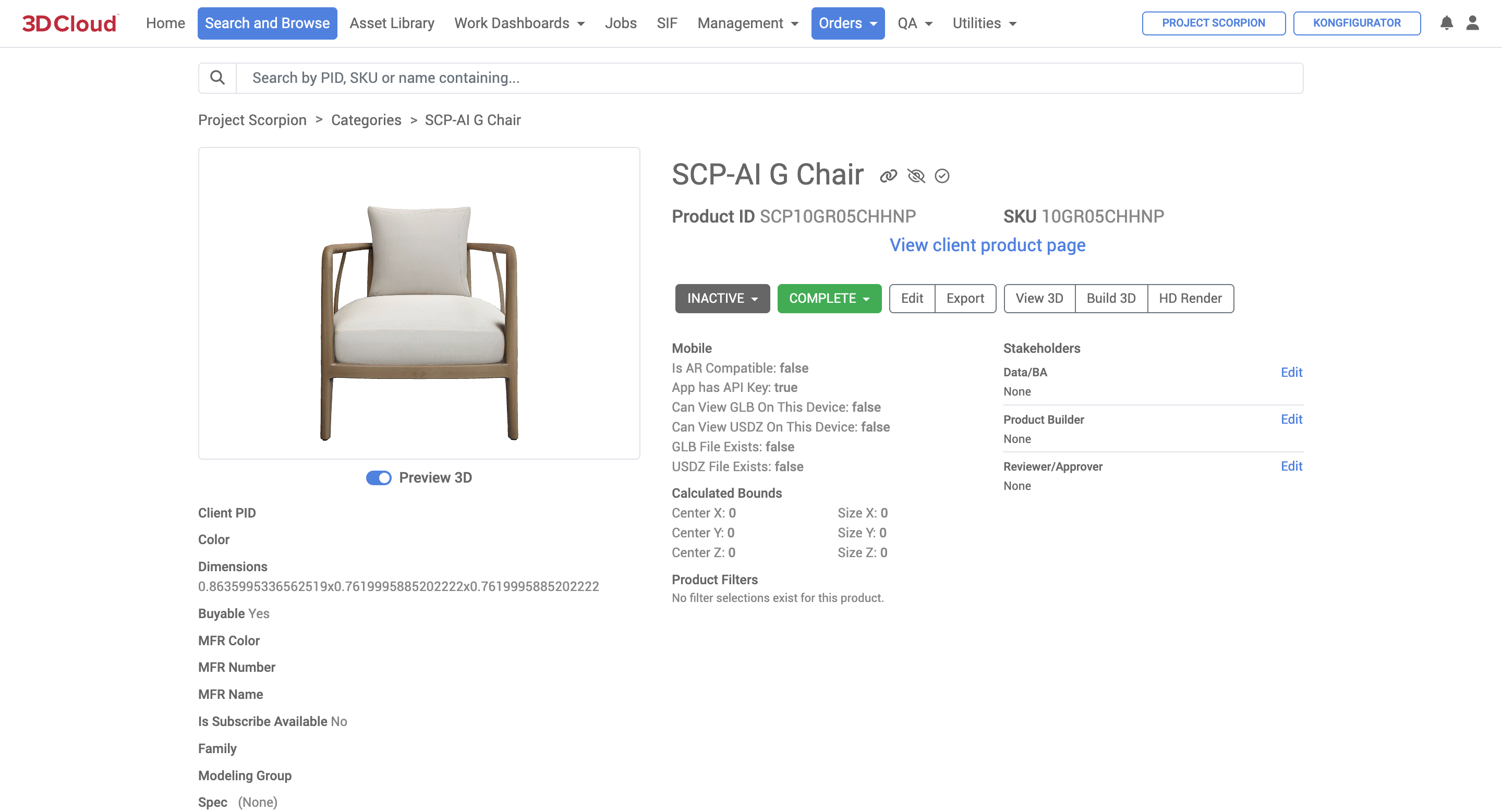
Download Final Mesh
Final 3D mesh files can be downloaded from the final 3D in these formats: .glb, .usdz. fbx
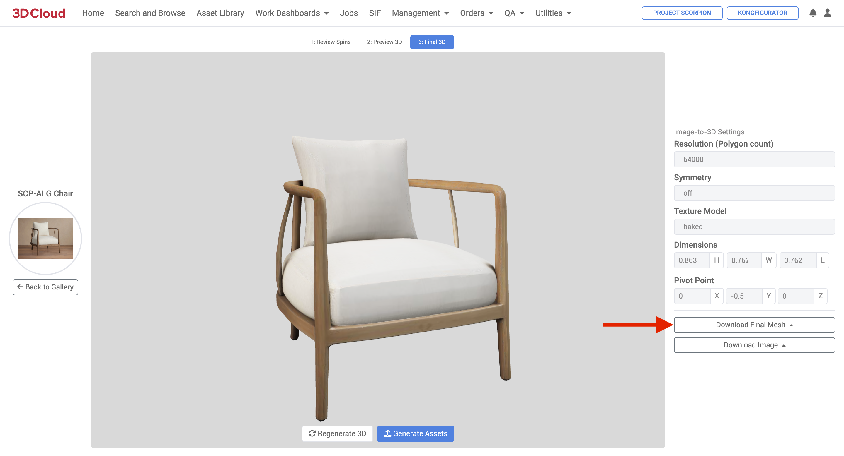
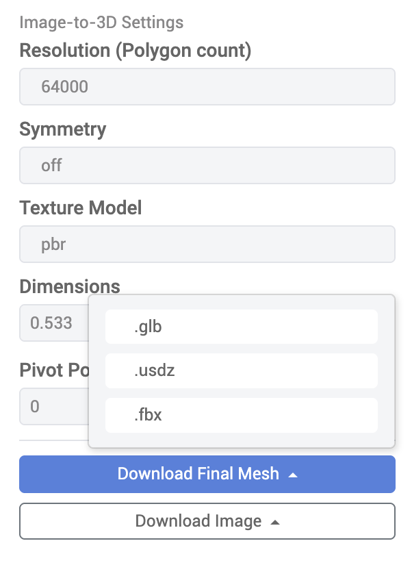
Download Image
From the final 3D preview page you can also download the first reference .jpg or a transparent .png (background masked and removed) of the first reference image.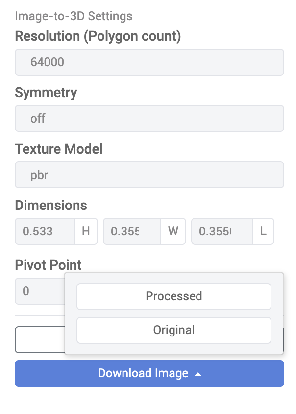
Note: Further R&D to upscale rendered images using generative AI techniques is an area of ongoing exploration.
Application Alerts
The 3D Cloud AMS Application Alerts feature allows for the creation of custom scheduled system alert messages for users. Each message can be one of three types:
Notification
Version_Update
Maintenance_Window
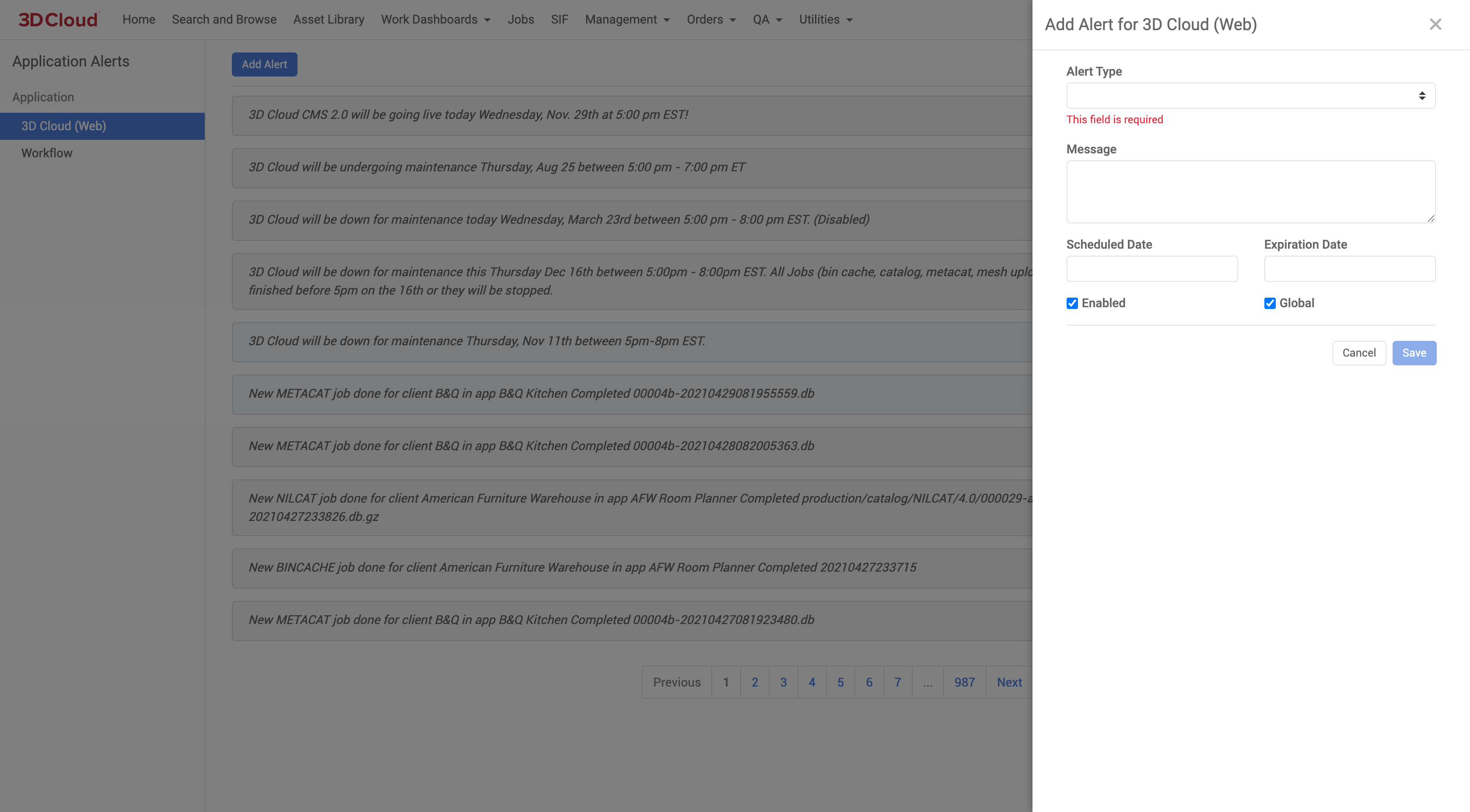
.png)
Asset Manifest
In the 3D Cloud AMS, the Asset Manifest is a client-specific data repository that contains configuration information for client and client apps. The manifest is effectively split into two sections: Asset Configuration and Client App Configuration. The Asset Manifest serves as metadata used by a running client app to allow it to download appropriate client, app, and product data.
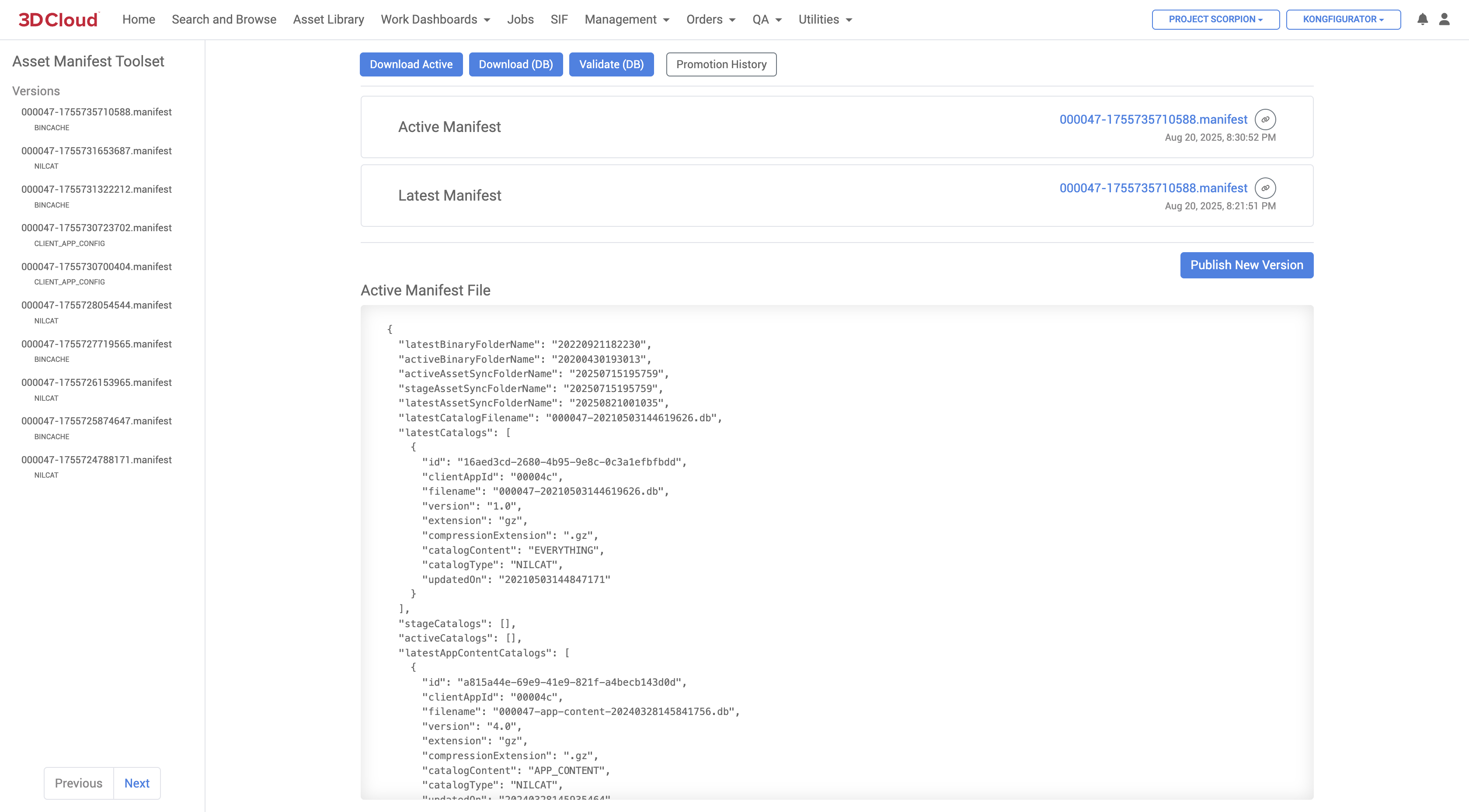
Asset Configuration
Asset Configuration contains entries of metadata for different assets, such as NILCATs, bin-cache files, and ARCATs. The metadata is made of up the catalog version, catalog type and filename, among other items. Each metadata is specified as an entry in the Asset Manifest based on three discriminators:
The client application
The client application environment: Latest, Staging, Active.
The asset version. Entries are created based on the version of a catalog generated.
Assets are typically versioned based on when they are generated and are given a timestamp. Each client application for each environment can refer to different versions of every asset. When assets are generated, they are immediately eligible to be set for an app’s Latest environment. Users can promote assets from Latest to Staging and/or Active via 3D Cloud.
Along with asset information entries, the Asset Manifest contains global and client level information such as service environment and storage path URLs.
Client App Configuration
The asset manifest also contains entries for client app configurations. The configurations specify settings for Style Kit, Blueprint, and lighting.
Uses
Like with the specified assets, the Asset Manifest itself is versioned and is promoted from Latest to Active. Client apps will download the Asset Manifest based on whether the app is running on latest or active environment. With the Asset Manifest, the app can then load the appropriate catalog, product and app configuration data. Asset Manifests are viewed in 3D Cloud for each client (provided the user has permissions) and are represented as a JSON document.
Specifications
The Asset Manifest is a dynamic document stored in the database. A snapshot file is generated when specified in 3D Cloud as either the Latest or Active version as a JSON file with a name of [client id].manifest. Note that Asset Manifest data cannot be modified directly through 3D Cloud. Asset Manifests can only be updated by generating new catalog data or promoting catalog data via 3D Cloud. The client app config section can be updated through the client app config editor in 3D Cloud.
Batch Asset Versions
The Batch Assets Versions tool was created to bulk activate vcn assets versions/variants (Meshes, Textures, Images). A list of vcn’s is entered or uploaded and each asset can be manually “Set as active”.
Example. An AMS user has a need to update Thumbnail images for a quite a few active products. When we add the thumbnail to an active product, typically one would need to go in to each asset manually and "activate" (click the button) due to the product being in state 1. With this tool the user can bulk activate a list of thumbnails.
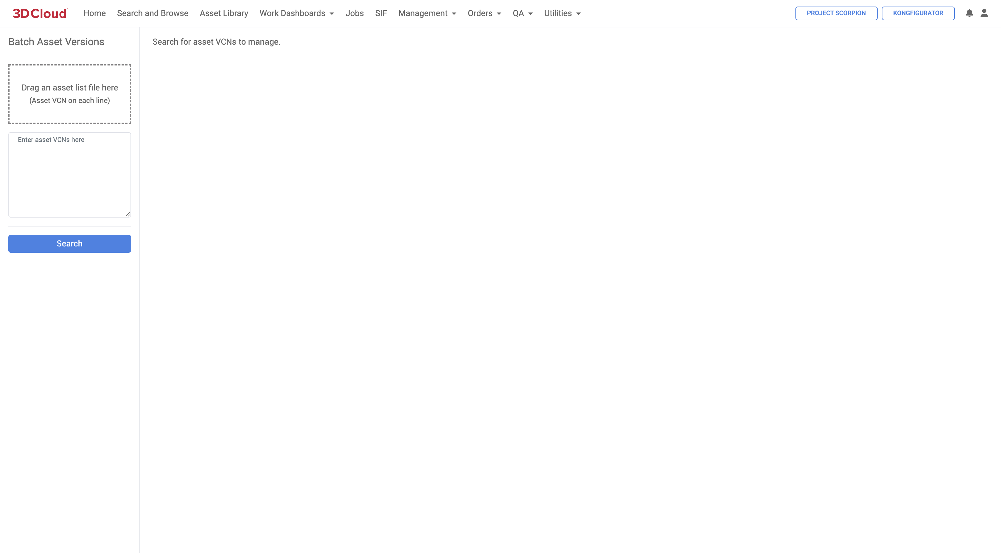
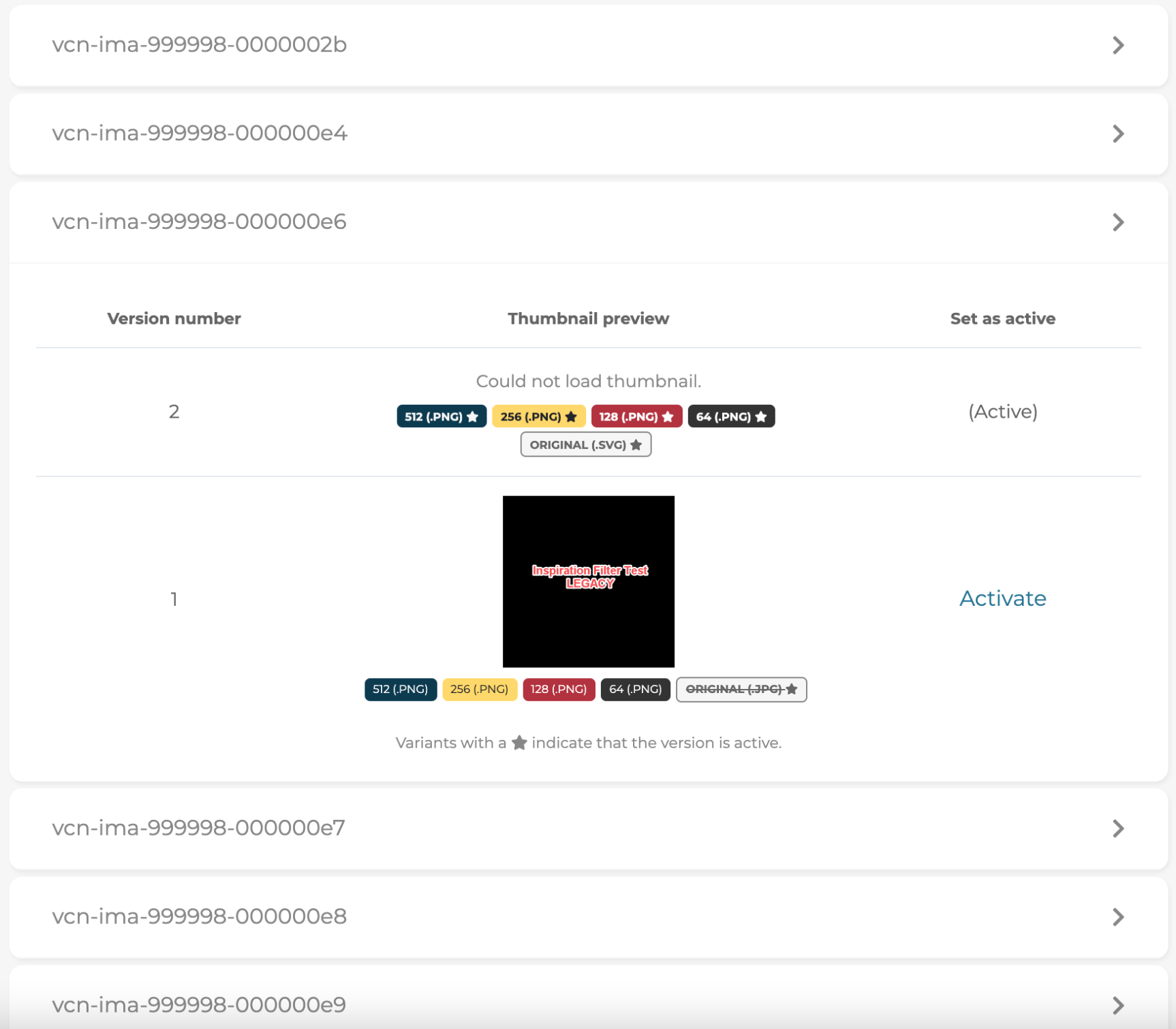
Batch Image Toolset
The 3D Cloud AMS Batch Image Toolset is a feature used in for processing images in bulk.
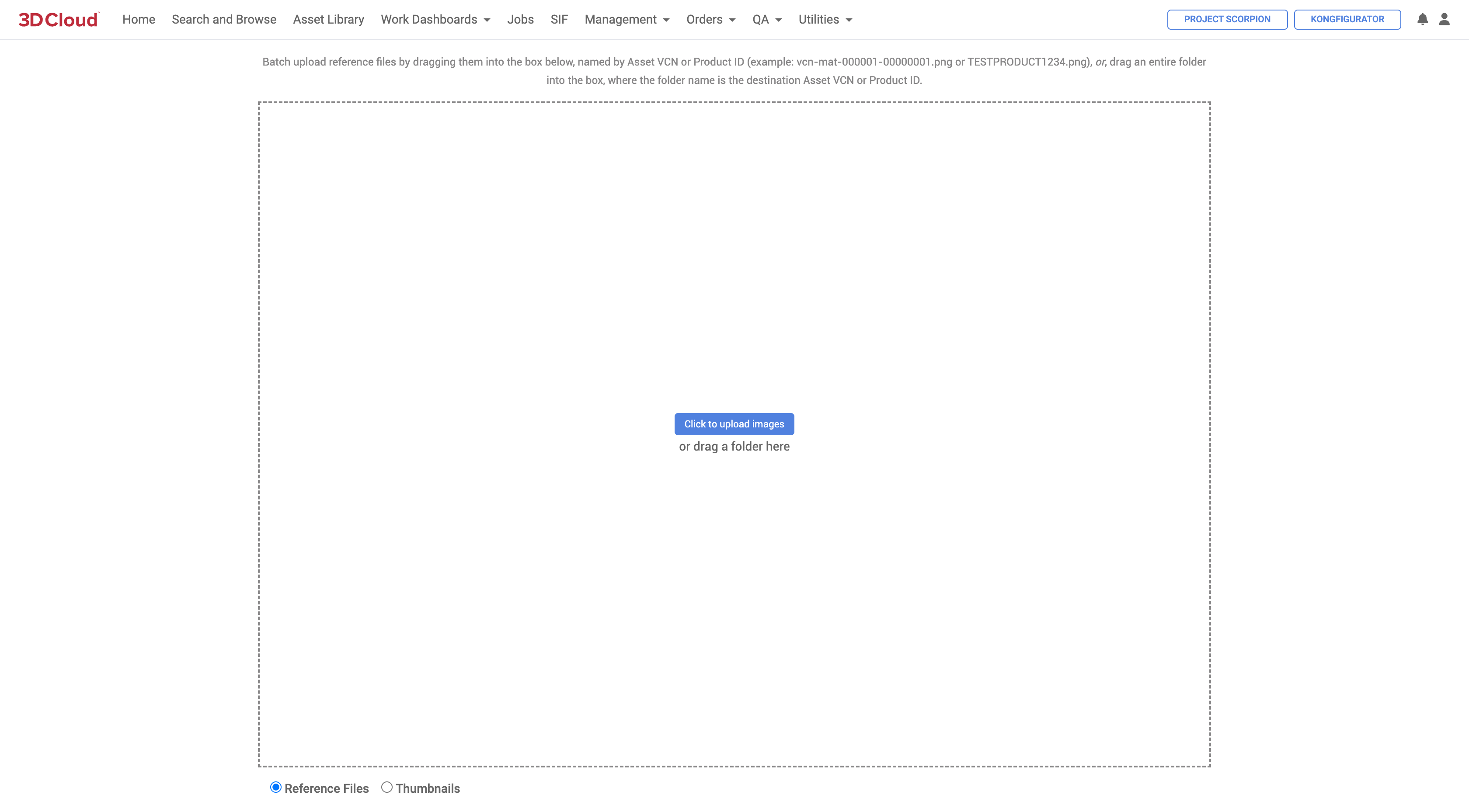
Here are some key points about its functionality:
Image Processing: When using the Batch Image Toolset, if a folder is uploaded where the folder name is the destination Product ID, only the first image inside the folder will be processed, and the rest will be ignored
Thumbnail Management: The toolset is used for uploading and managing thumbnails. When uploading thumbnails for active Product IDs (PIDs), new versions of thumbnails need to be manually activated through Thumbnail Versioning
Integration with Other Tools: The Batch Image Toolset can be used in conjunction with other tools like Thumbelina for resizing images before processing them through the toolset
Known Issues: There are known issues such as duplicate entries when uploading thumbnails to virtual products, which can be resolved by uploading thumbnails to individual products instead
Usage in Asset Management: The toolset is part of the broader 3D Asset Management System, which includes features for batch uploading reference images and managing asset orders
This toolset is particularly useful for managing large volumes of images and thumbnails efficiently within the 3DC platform.
Bin Cache Toolset
Bin caches are the way the 3D Cloud AMS manages and optimizes saved data retrieval and storage. The Bin Cache Toolset is a versioning tool that allow data changes to be reflected in final Client Applications without requiring a complete refresh of the entire dataset.
Whenever modifications are made at the product or category level, a Bin Cache must be run to ensure that these changes are visible in the application.
The 3D Cloud platform uses three primary catalogs (structured data), named NILCAT, METACAT and ICAT. These catalogs are created either automatically after a Bin Cache job run, or manually.
NILCAT is the main catalog for product/app data.
METACAT is for pricing and extra metadata (used if your app needs pricing).
ICAT is for supporting multiple languages/regions.
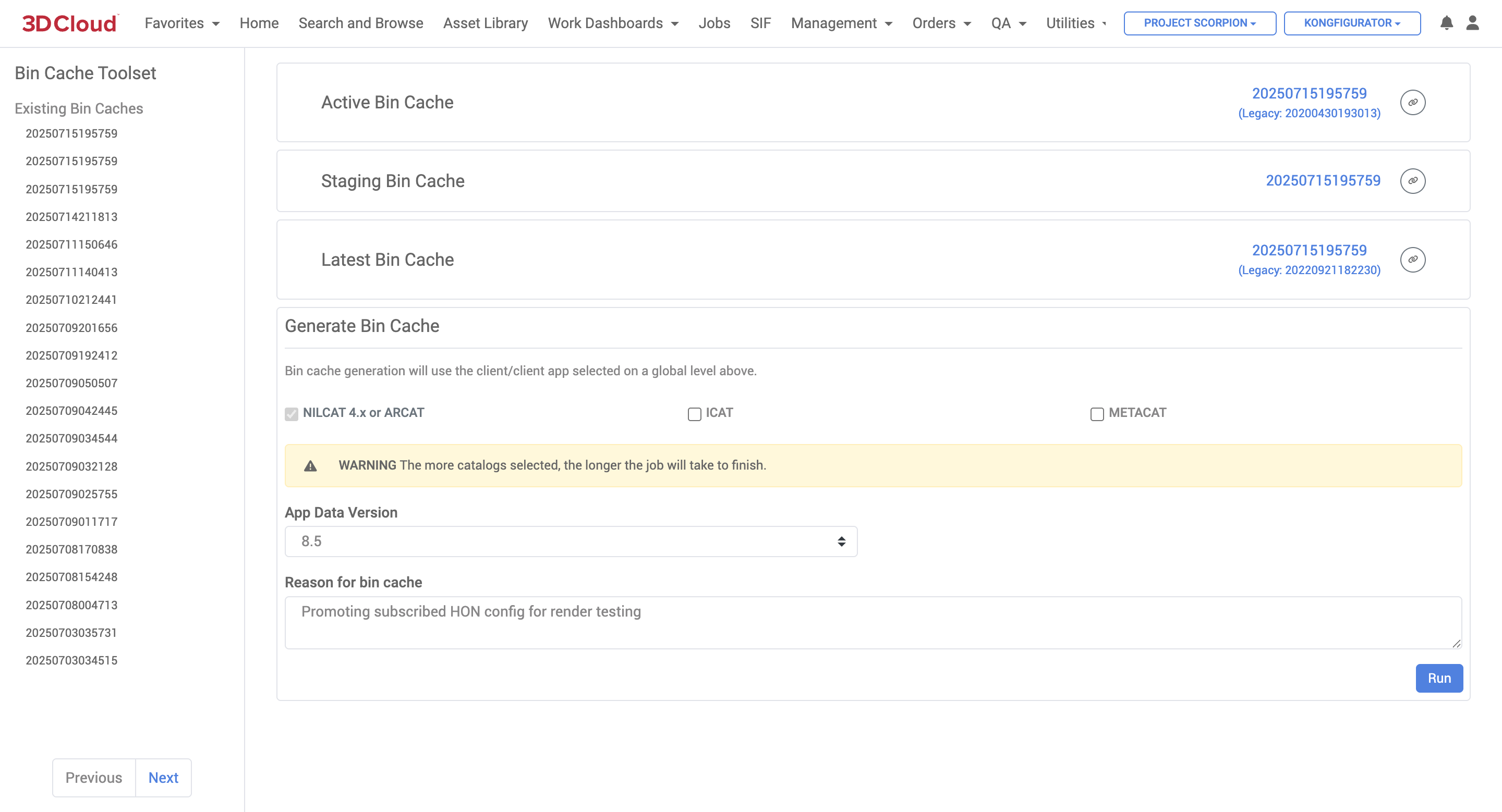
How to Run a Bin Cache
By following these steps, you can effectively run a Bin Cache and promote an Asset Manifest within your system.
Confirm the Client and Application: Ensure you are on the correct client and application for which you want to run the bin cache.
Access the Bin Cache Toolset: Navigate to the Utilities menu and select the Bin Cache Toolset.
Select Options: Ensure that the necessary options are selected. Typically, the "NILCAT 4.x or ARCAT" option is always selected, while "ICAT" is not (for supporting multiple languages/regions). The "METACAT" option may also be selected if it contains relevant data.
Set Data Version: Confirm that the app data version is set to the latest version.
Provide a Reason: Enter a reason for running the Bin Cache (optional, but can be helpful for tracking).
Run the Bin Cache: Click the blue “Run” button on the lower right, and “OK” to the “Are you sure?” confirmation screen to execute the Bin Cache process and wait for it to complete.
Check Status: Monitor the Job status of the Bin Cache via the progress bar on the Jobs → Job Type: Client Asset page. A green check mark indicates success, while a red exclamation mark indicates failure.
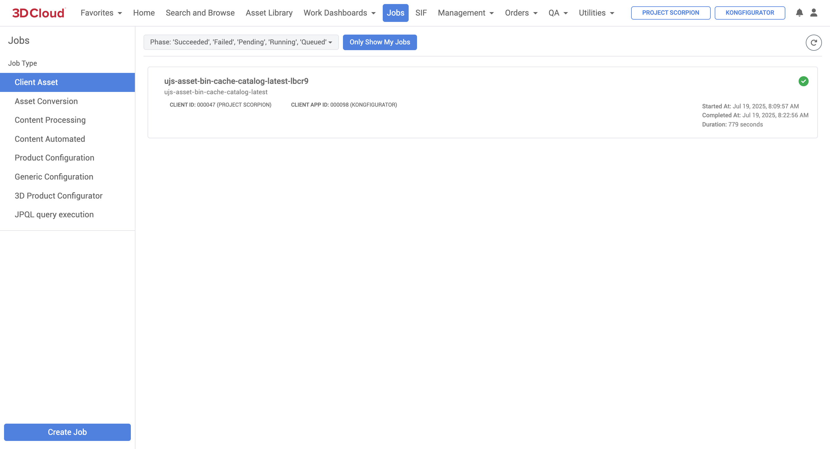
Promoting an Asset Manifest
The Asset Manifest is a client-specific data repository, represented as a JSON file, that serves as a “roadmap” for client applications telling them what assets to use and where to find them. An asset manifest can be updated with data changes but currently must be promoted to “Active” state manually.
Access the Asset Manifest: After successfully running the Bin Cache, go back to the Utilities menu and select Asset Manifest.
Verify Versions: Check the latest version number in the asset manifest and ensure it differs from the active version (you can compare the date/time stamps).
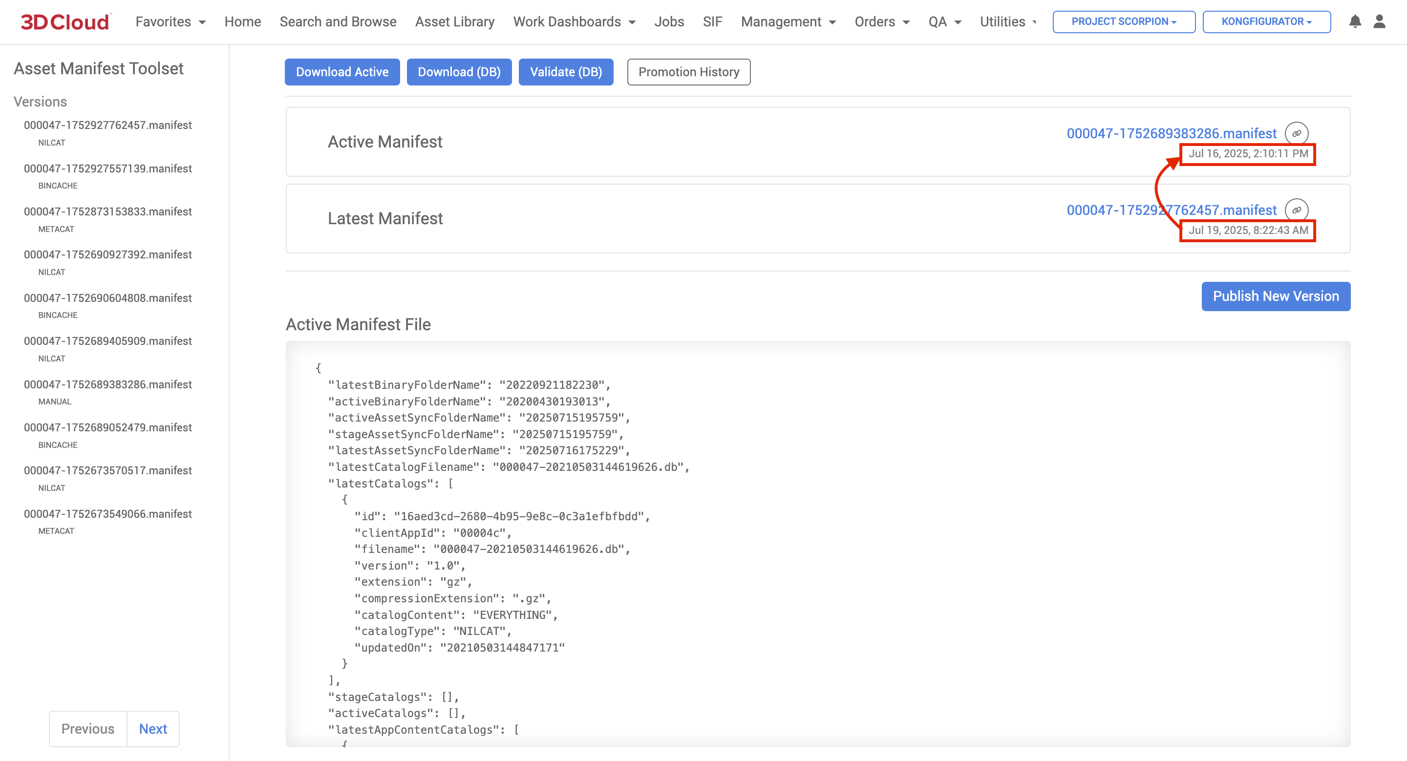
Validate the Database: Click the blue Validate (DB) button to validate the database and confirm the entries are in sync with the database.
Review Differences: Click on the most recent Version in the left hand “Versions” side panel (should be at the top of the list) and a “Diff with Active” will be displayed. Highlighted red and green lines indicate changes/differences between the latest version and the active version, which you can check.
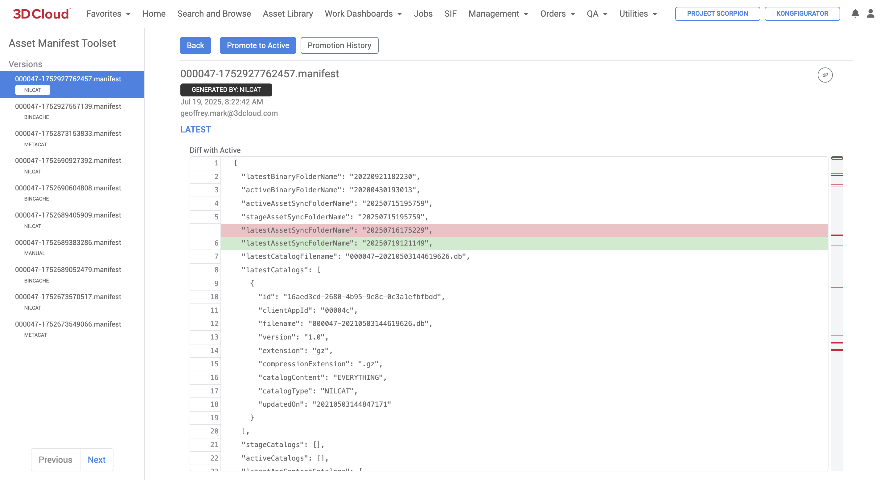
Promote to Active: If the versions are confirmed to be different and there are no issues, click the blue Promote to Active button and “OK” on the confirmation screen to promote the latest version to active.
Confirm Promotion: After promotion, verify that the active version now matches the latest version in the asset manifest.
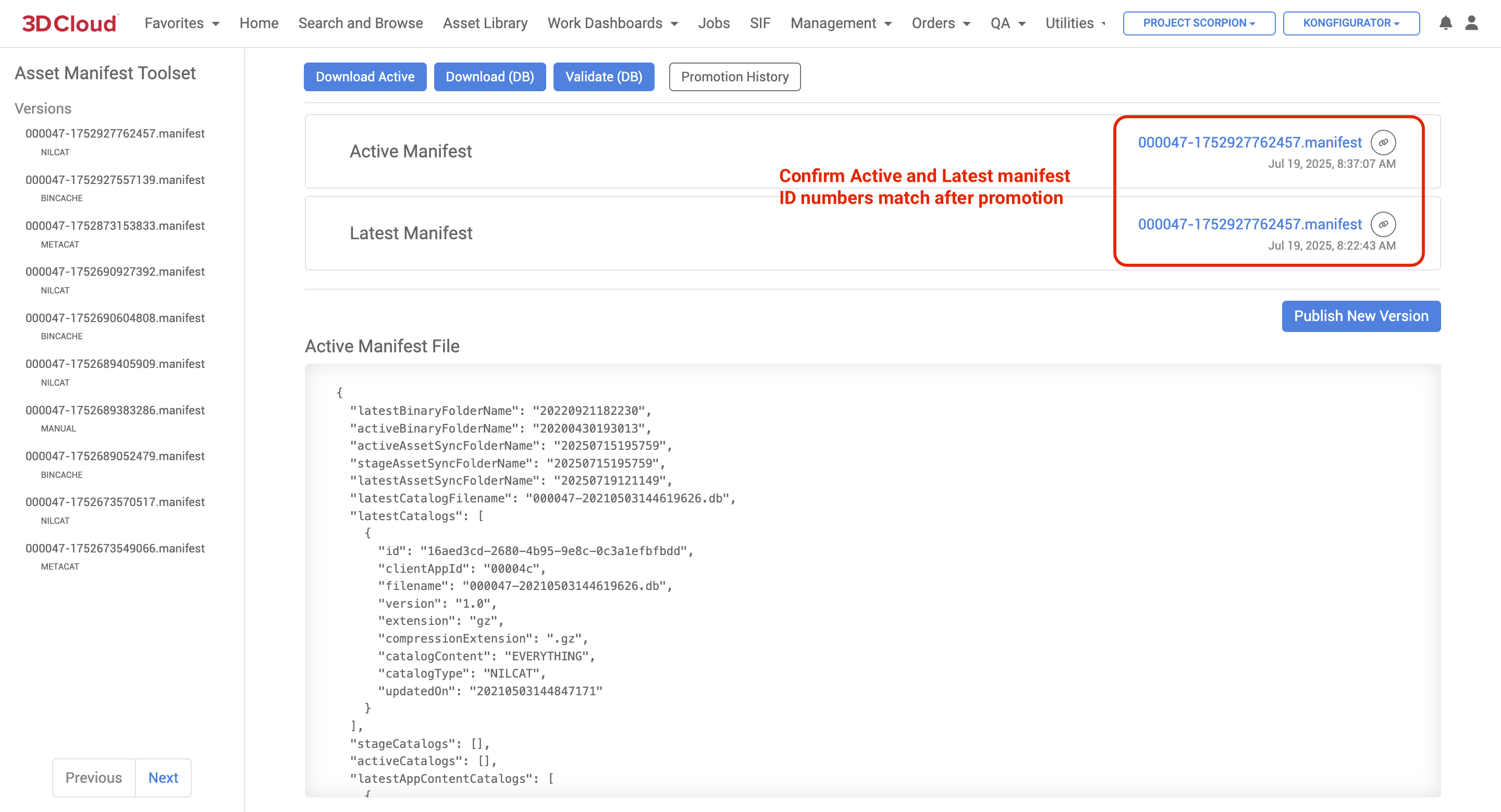
Final Check: Ensure that the changes are reflected correctly in the application and that everything is functioning as expected.
Catalog Toolset
The 3D Cloud AMS Catalog Toolset Utility is used for managing and promoting catalogs within the platform.
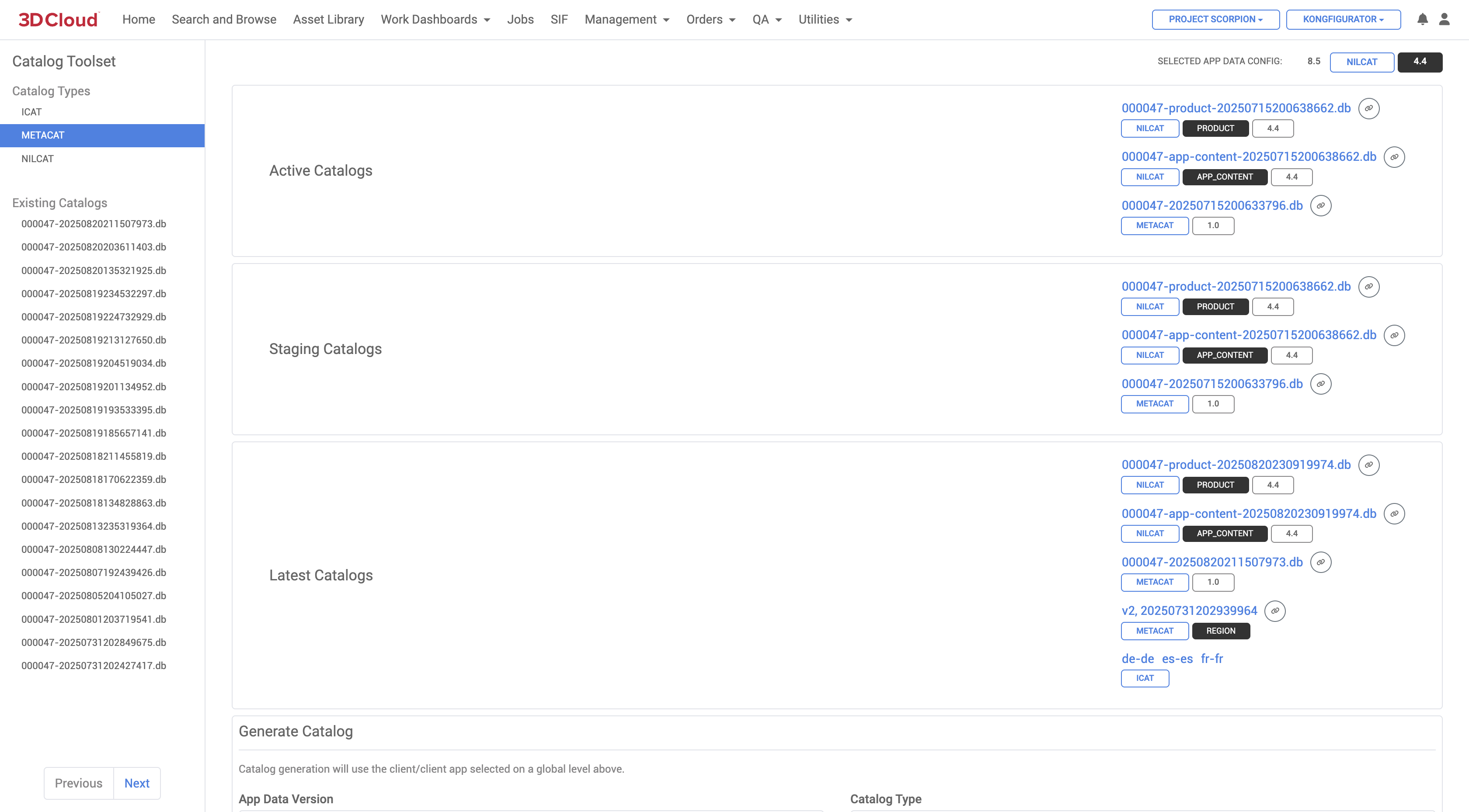
It allows users to:
Promote Catalogs: Users can promote catalogs from the latest version to staging or active states. This involves selecting the appropriate catalog type and running the promotion process
Manage Catalog Versions: The tool helps in managing different versions of catalogs, including NILCAT, METACAT, and others. Users can select and run specific versions as needed
Copy Catalog Names: The toolset includes features like a copy button for catalog names, making it easier to manage and reference different catalogs
Run Catalogs with Bin Caches: Users can select which catalogs to run with a bin cache, allowing for combinations of NILCAT, ARCAT, ICAT, and METACAT
Handle Catalog Metadata: The toolset allows for the input and management of metadata associated with catalogs, such as names and descriptions.
Overall, the Catalog Toolset Utility is designed to streamline the management and promotion of catalogs within the 3DC environment, ensuring that the latest data is available and correctly configured for use in applications.
Client Dashboard
The 3D Cloud AMS Client Dashboard utility provides a client-level summary of base model count, material-only count and mesh exclusions.
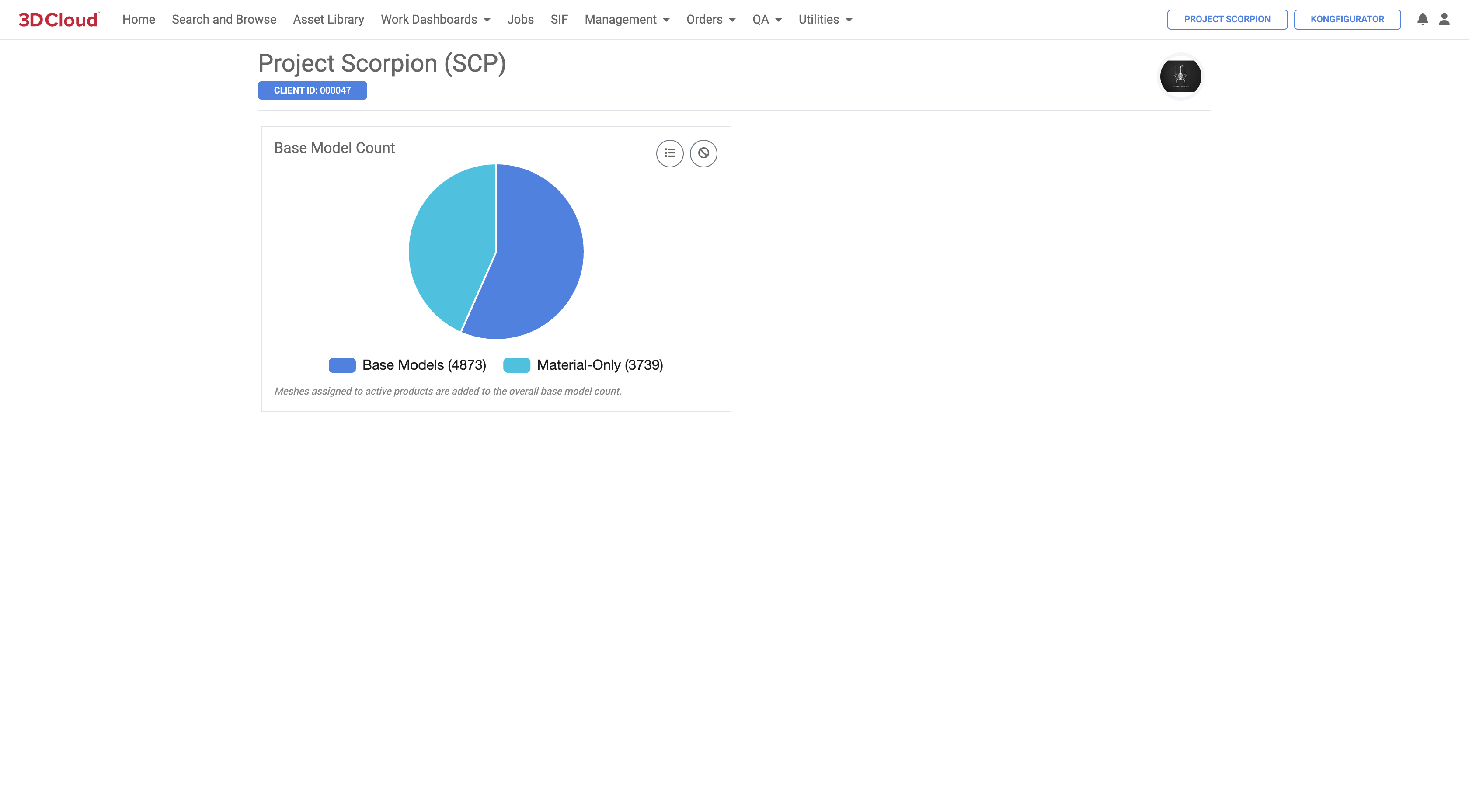
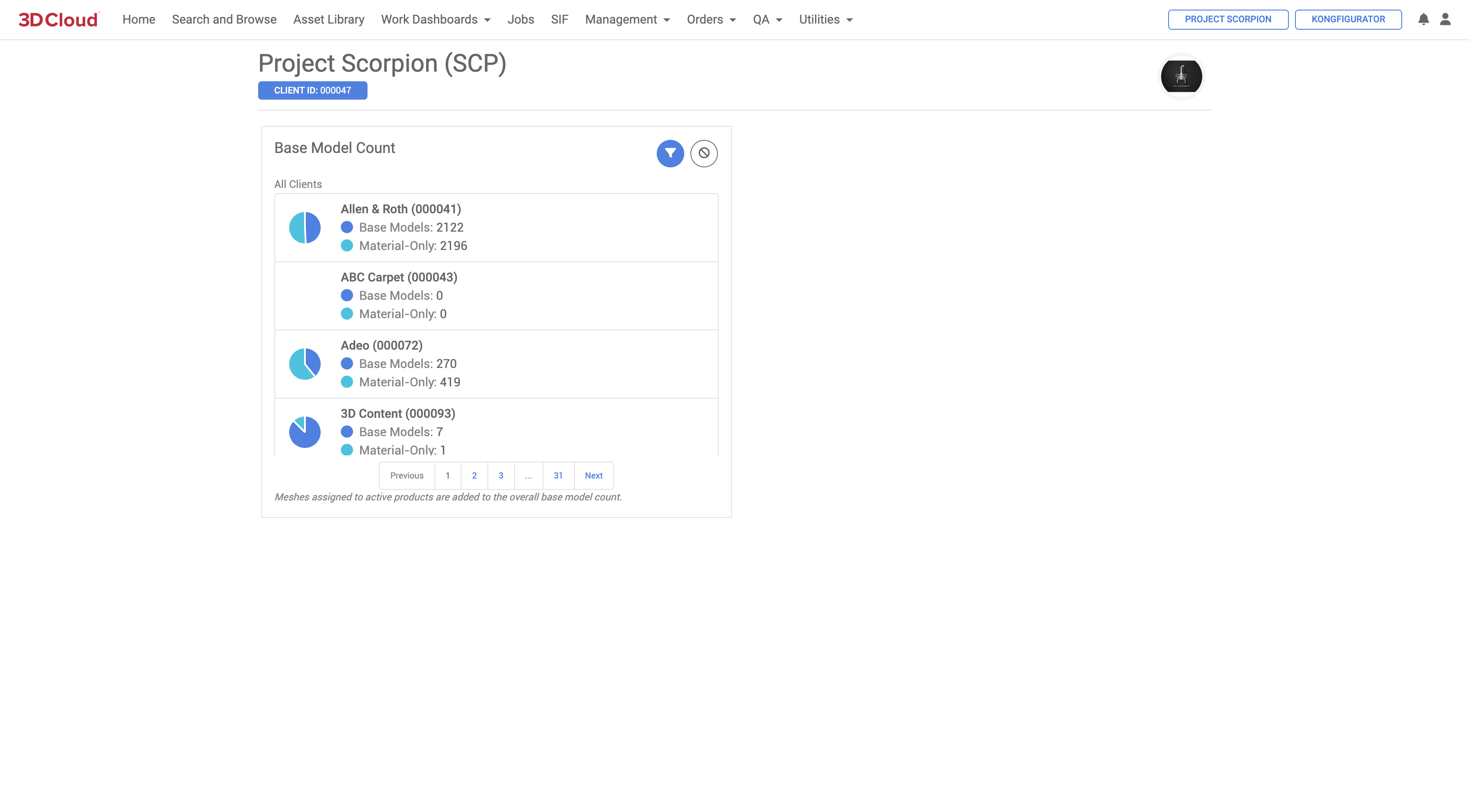
Content Discovery - Scraper
The 3D Cloud AMS Content Discovery - Scraper Configuration tool (available at Utilities →Content Discovery - Scraper) allows for the creation of configurations that can be used to gather product metadata and reference imagery directly from client websites.
Typically, scrapers are set up by 3D Cloud developers (requires a development ticket to be worked) and tested by Data/BA associates. Scrapers are employed during the asset ordering Discovery process, if client-supplied references are not obtained by other file transfer means.
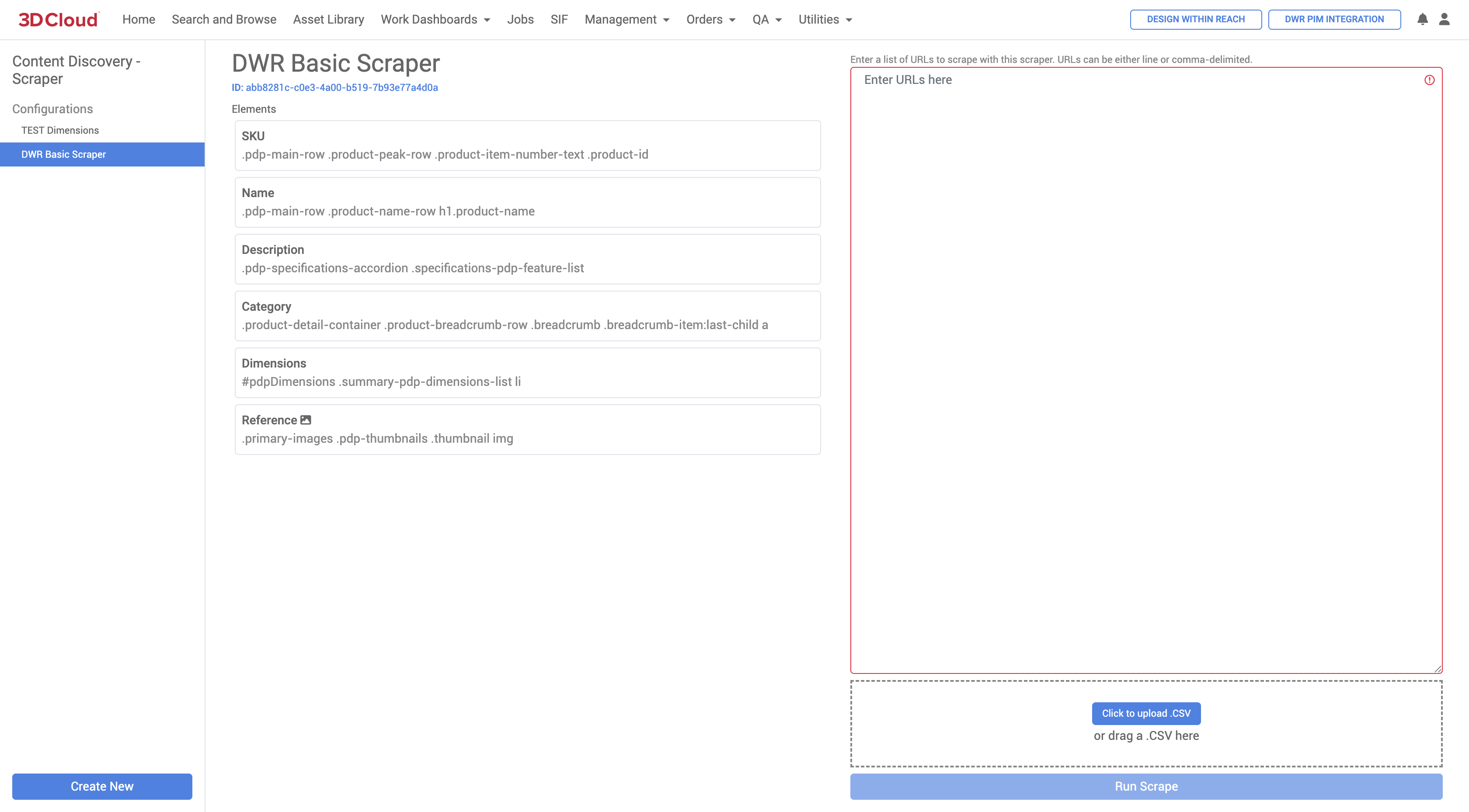
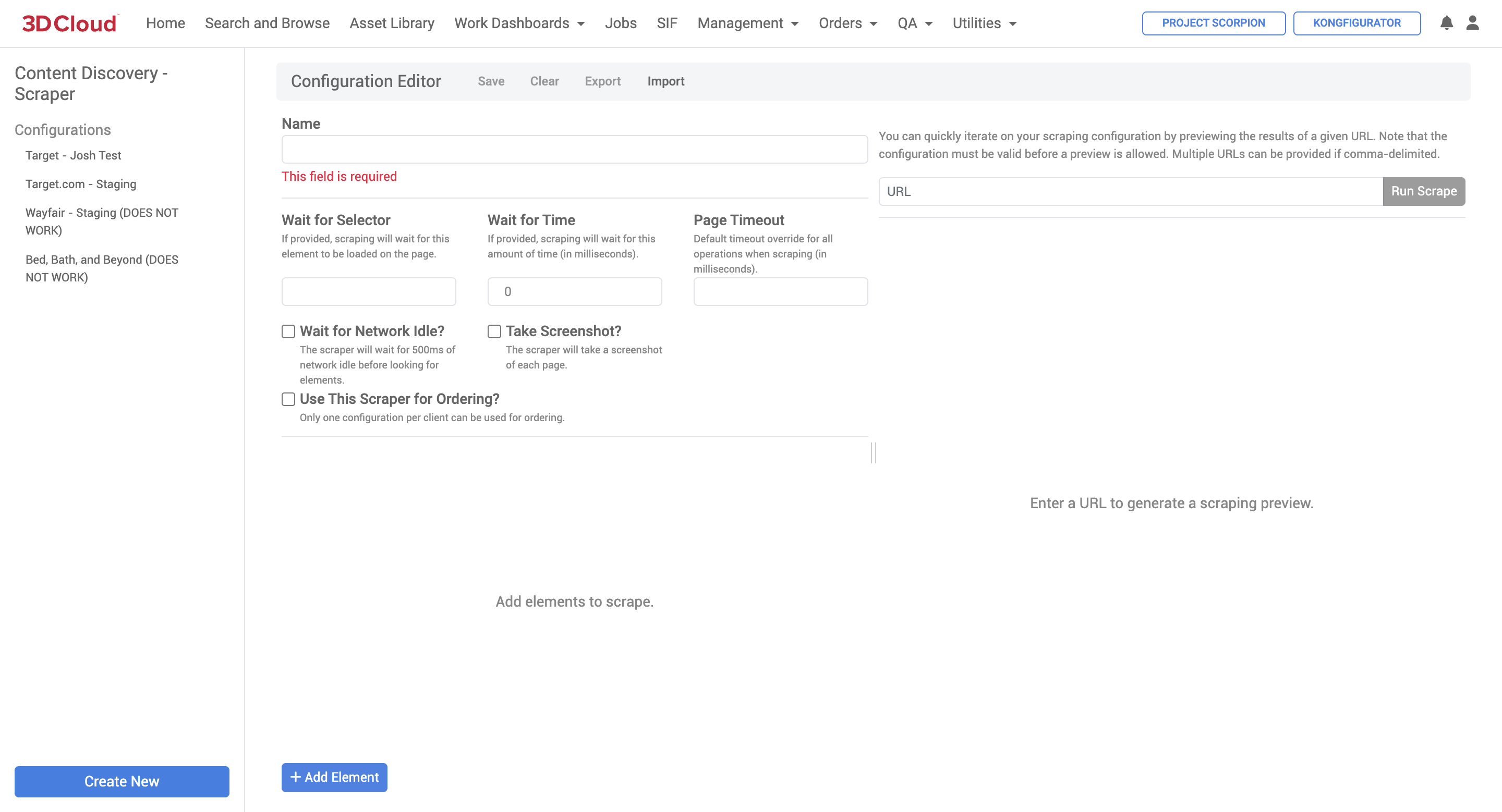
Options
Wait for Network Idle?
If checked, the scraper will wait for network activity to be idle for at least 500ms on the client website before starting the scrape. This is useful when there is a lot of asynchronous loading of content. If you’re noticing that content isn’t being retrieved even though the selectors are accurate, try this option.Wait for Selector
Similar to
Wait for Network Idle?, the scraper will wait for this CSS-style selector to be present on the page before scraping begins.Note: The default timeout for wait operations is 20 seconds.
Scraper Elements
ID
The unique identifier for this element. Results will key off of this ID.
Label
The label for this element.
Selector
The CSS-style selector that will be used to find this element on the page. This can retrieve multiple elements, which can then be filtered later. See CSS selectors - CSS | MDN for more detail on creating selectors.
Attribute
The HTML attribute to use as the value for this element. Especially for retrieving the
srcorhrefelements on images or links.Element Counts (First, Last, nth)
If multiple elements are retrieved by the selector, you can select a particular result using these flags. If multiple elements are retrieved and none of these options are selected, all values will be written to the output.
Text Counts (First, Last, nth)
Similar to Element Counts, this will select a particular result when multiple text nodes are selected.
Pattern
A regex pattern that must be matched in order for this element to be returned. Regex groups can be used to target specific content (for example, the pattern
^3D (.+)would match text beginning with “3D “, but would only return the text after “3D “.Format
A string that can be used to format a result after it’s selected. Use
%value%to inject the value’s content. For example, if the string “Marxent“ was returned by this selector, the formatformatted_%value%_testwould return “formatted_Marxent_test” in the results.Split By
The character(s) by which a selected value will be split by in the result set. For example, the result “a,b,c” could be split into the array [“a”, “b”, “c”] if the
,character is specified.Delimiter
If multiple values are returned by this selector, they will be combined into a single value using this delimiter. The opposite of “Split By”.
File Controls
Download Image?
If the element selected is an image, it will be downloaded as it exists on the page (rather than a separate download via its URL) using a canvas element. Useful when a URL isn’t available, but also fragile depending on the client website’s setup.
Download File?
Downloads the file at the URL(s) selected by this element. Make sure the resulting value of this selector is a URL, otherwise this option won’t do anything.
Use as file key?
By default, images will be placed in a directory named as the URL of the page being scraped. If this option is provided, images will be placed in a directory named as the resulting value of this element. For example, maybe you’re selecting an element ID “sku” from the client website and want to place images in a directory with that SKU’s value.
File Protocol
If a file protocol isn’t available on the selected URL (maybe it’s a relative URL path), this option can be used to specify it. Defaults to https if not provided.
File Directory
Files downloaded by this selector will be placed in a directory of this name (in a subdirectory named with the file key above).
Preview
Scraping configurations can be previewed against a particular URL as long as the configuration is complete and valid. Multiple URLs can be provided if comma-delimited.
Note: The scraped content in JSON format will be displayed by default, but the full scraping result, including files, can be downloaded using the “Download Result” button.
Content
The 3D Cloud AMS Content Utilities section contains numerous tools for managing 3D assets in the platform.
Bulk Asset Download
The Bulk Asset Download content utility allows users to download multiple product assets simultaneously from a provided list. The Bulk Materials tool can be found under Utilities → Content → Bulk Asset Download.
Users can download different components of a product as a single .zip file, including:
Meshes (by list of asset VCNs in a sheet or entered into the online input area)
Materials (Download Pre-multiplied, PBR, or Single .zip options)
Bulk Materials
The Bulk Materials content utility enables the management of multiple material assets simultaneously.
The Bulk Materials tool can be found under Utilities → Content → Bulk Materials.
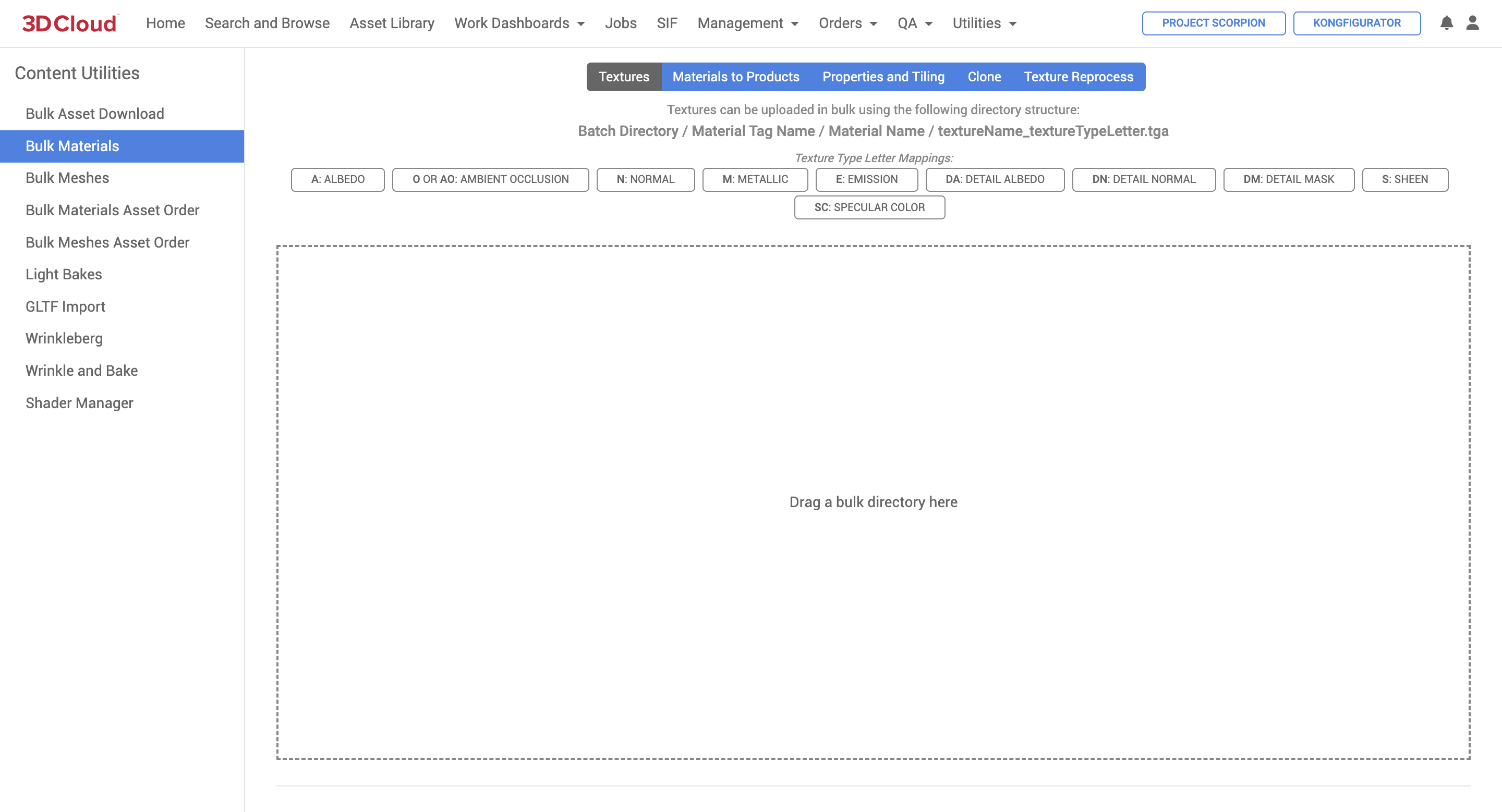
There are 5 “sub-tools” within Bulk Materials (Textures, Materials to Products, Properties and Tiling, Clone and Texture Reprocess). You can toggle between these tools by clicking your desired tool from the blue options bar.
![]()
Textures
Materials to Products
Properties and Tiling
Clone
Texture Reprocess
Textures
The Textures content tool accepts uploads of textures that have a very specific naming convention, which is outlined at the top of the tool page.
Batch Directory / Material Tag Name / Material Name / textureName_textureTypeLetter.tga
Note: The Material Tag Name has to exist in the client you are uploading to.
This is an example of a file structure for a texture.
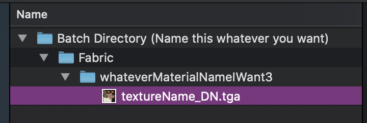
You can also have multiple material tags under one folder, and/or multiple textures under each tag like so:
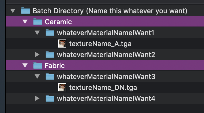
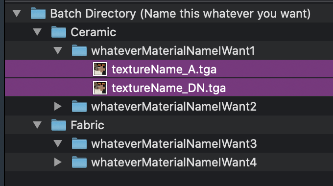
Once you have your files organized accordingly, you can drag the whole “Batch Directory” to the tool.
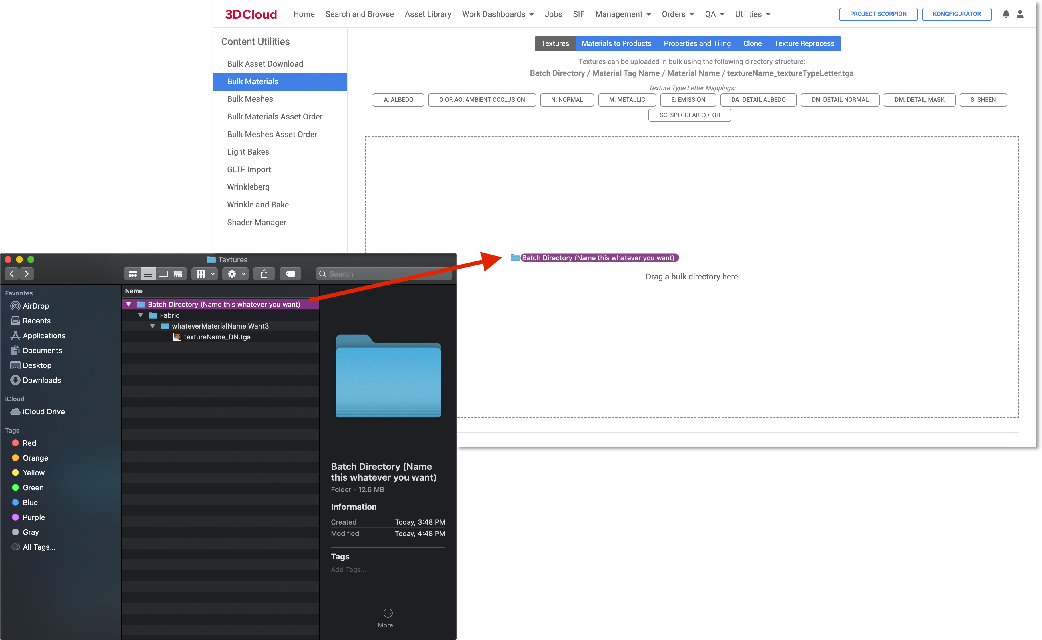
Note: Currently accepted texture file formats include TGA and PNG. JPG is not currently supported.
It will take a bit of time to kick off the job and show its progress.
Once the job starts, a progress bar will appear with an estimated time remaining.
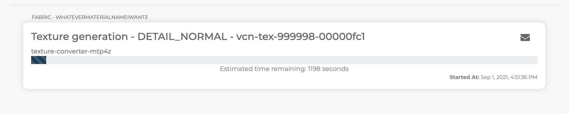
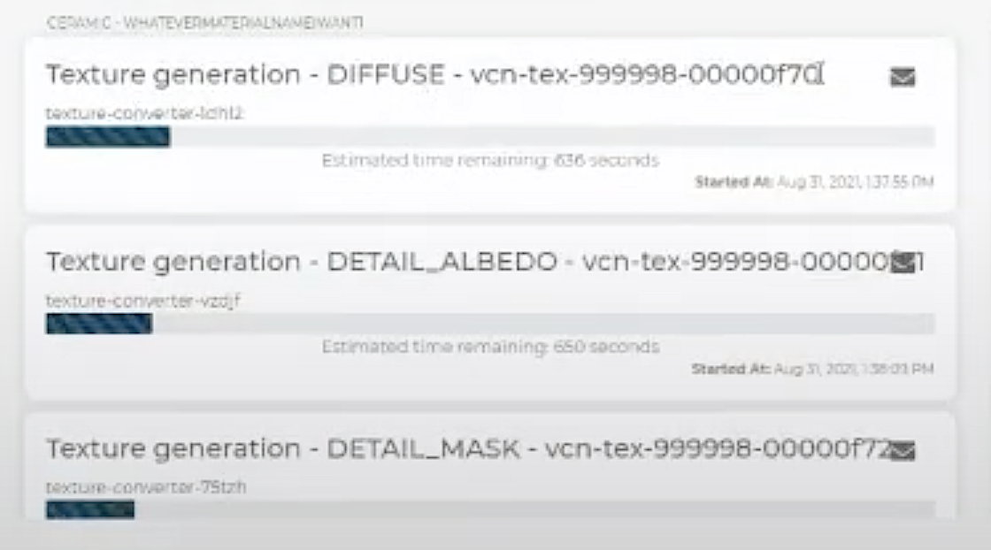
Another Example
While this content is processing, if you are planning on working on other tasks in the AMS, we recommend using a new tab or window of 3DC. If you try to leave this page or go to another content tool, this message will appear:
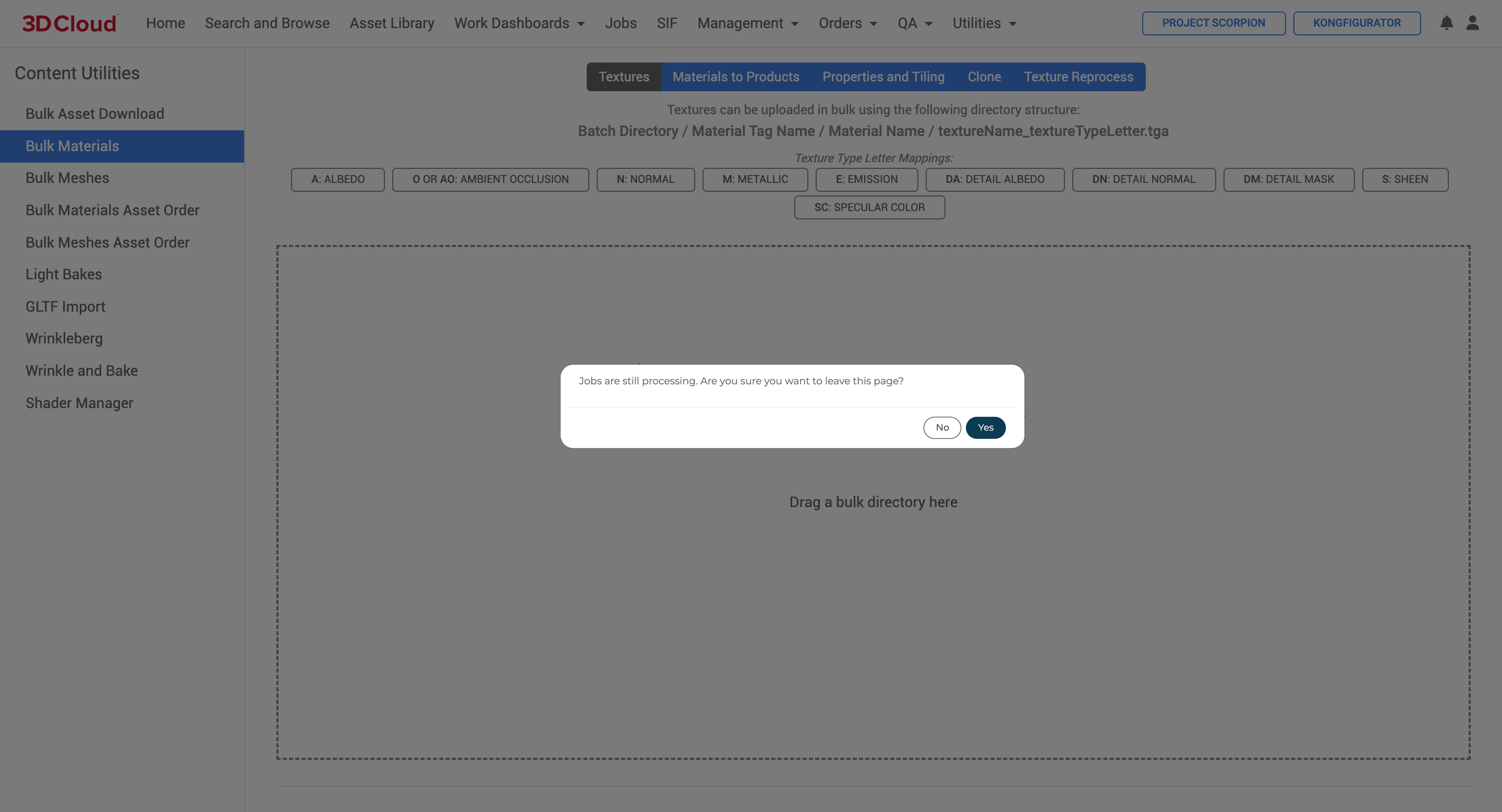
If you do leave, however, the status of the job will be accessible on the “Jobs” page under “Asset Conversion”. There is a bit of lag time between the Jobs page progress bar and the bulk materials queue progress bar, but they will be relatively in sync.
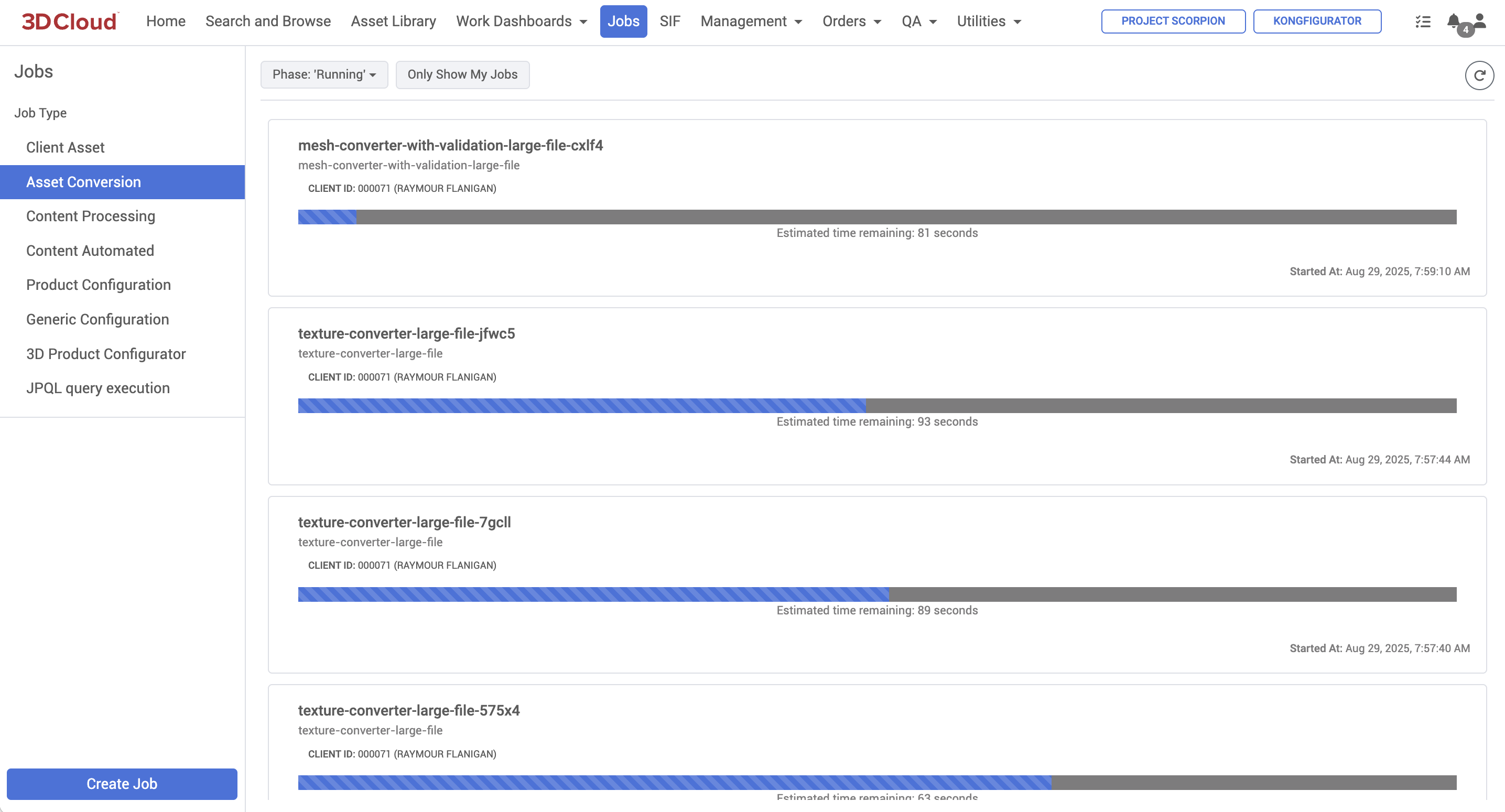
For each texture-converter- job, you can see the Tool and Envelope icon. The tool icon will show the job’s parameters. The envelope icon will show any errors that occur.
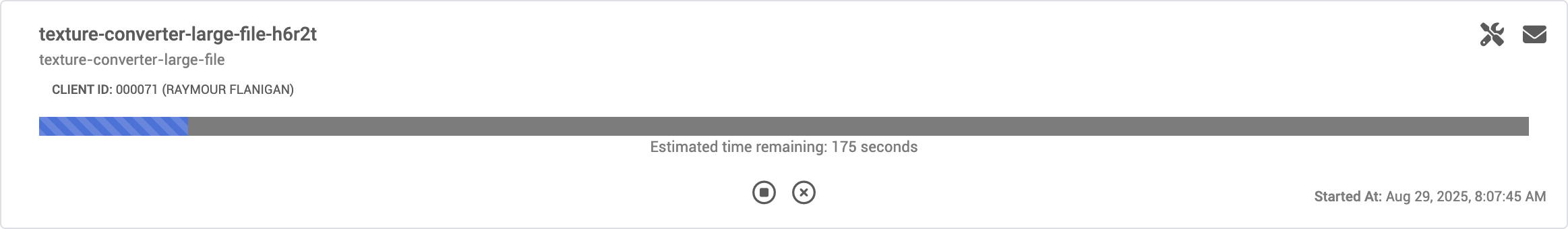
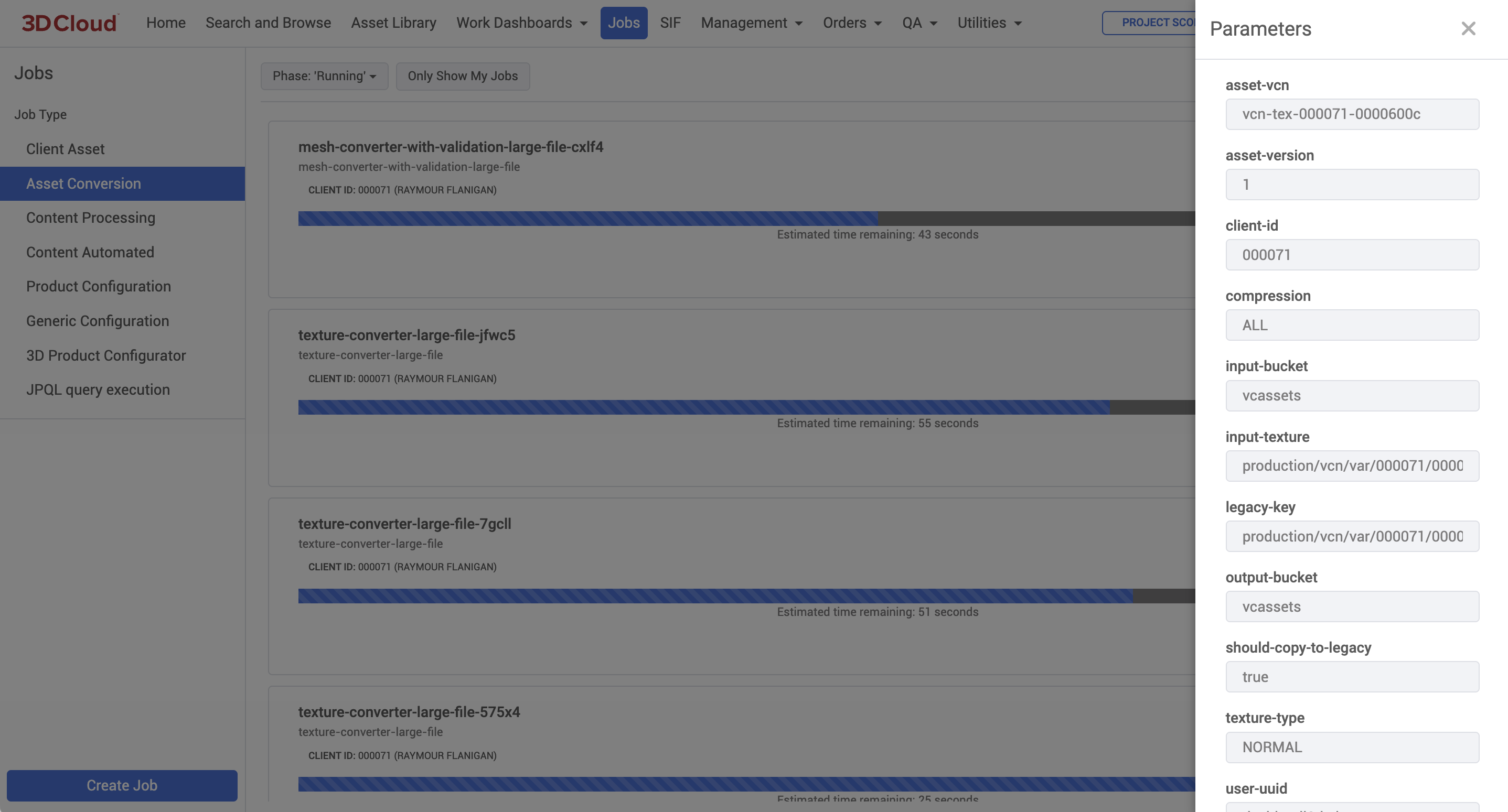
When the job finishes processing, it will look like this:
.png)
If a job fails, there will be a red “!” icon. The envelope icon will list any valid errors the job ran into. If there are no errors listed, click the arrow button to retry the job. We typically see success after retry.
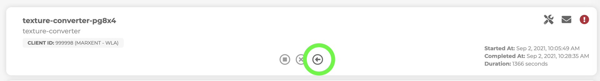
Materials to Products
The Materials to Products content tool uses the import of an Excel file to map materials to the desired products.
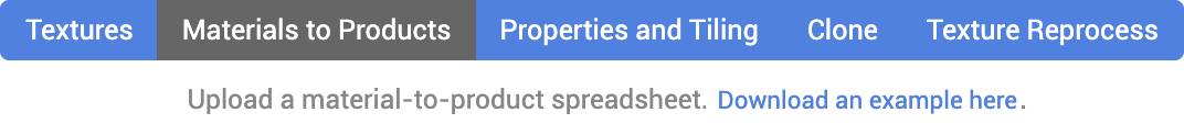
You can click “Download and example here” link to download an excel file template. The template and an example look like this: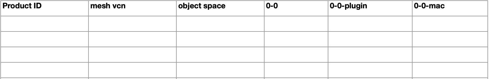
Examples of how to fill out this sheet would be:
![]()

Once the appropriate sheet is filled out, you can drag the file into the box, or browse for the file.
.png)
A loading screen will appear, typically the import is pretty quick. If you have 5,000+ materials, it may take up to 15 mins. When the import is complete, a message will appear at the bottom of the screen. If there are any errors they will show here too.
Properties and Tiling
The Properties and Tiling content tool offers bulk editing capabilities to adjust properties of a material with an Excel sheet import.
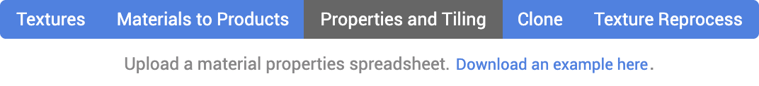
You can click “Download and example here” link to get a template Excel file for available fields to adjust.

You can edit as many or few fields as you’d like. If you don’t want to edit a field, you can leave that cell blank or remove the column.
One thing to note on the _Color and _EmissionColor fields only accepts 8 digit Hex values formatted like “FFA500CC”. The final two hex code values represent opacity. Do not include the “#” symbol or type a color name, like “Red”.
It’s also important to note that the _EmissiveMode field values must be spelled with all CAPITAL letters, like this:
ADDITIVE
LUMINOSITY
We do not currently support setting the _EmissiveMode to null via a bulk sheet upload.
Example of a filled out sheet for one material:
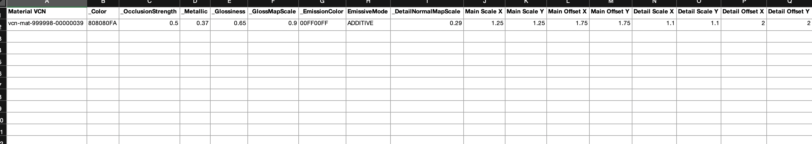
Clone
Cloning copies all components of the material including the textures and all of the set properties.
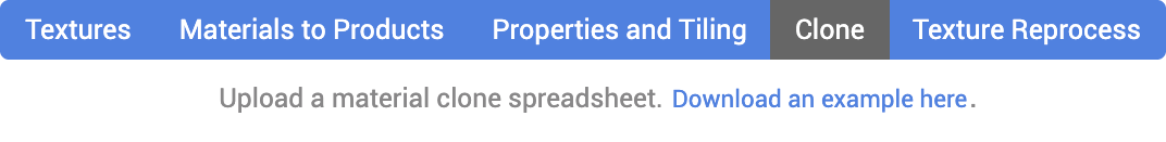
You can click “Download an example here” link to download an Excel template. When formatted and ready, it should look like this:
Like the other material tools, you can search for your file or drag it into the upload box. A message (or any error message) will appear at the bottom of the screen when completed.
Texture Reprocess
The Texture Reprocess content tool is used to process a list of texture asests to ensure that they are optimized for performance, compatibility, and visual quality across different platforms and devices.
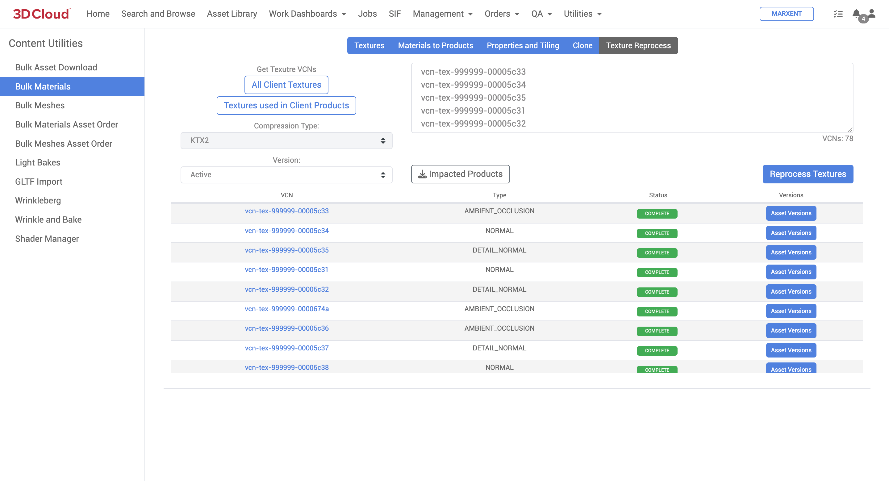
Bulk Meshes
The Bulk Meshes content tool enables the upload of multiple mesh assets simultaneously and works similarly to the Bulk Materials content tool. The Bulk Meshes tool can be found under Utilities → Content → Bulk Meshes.
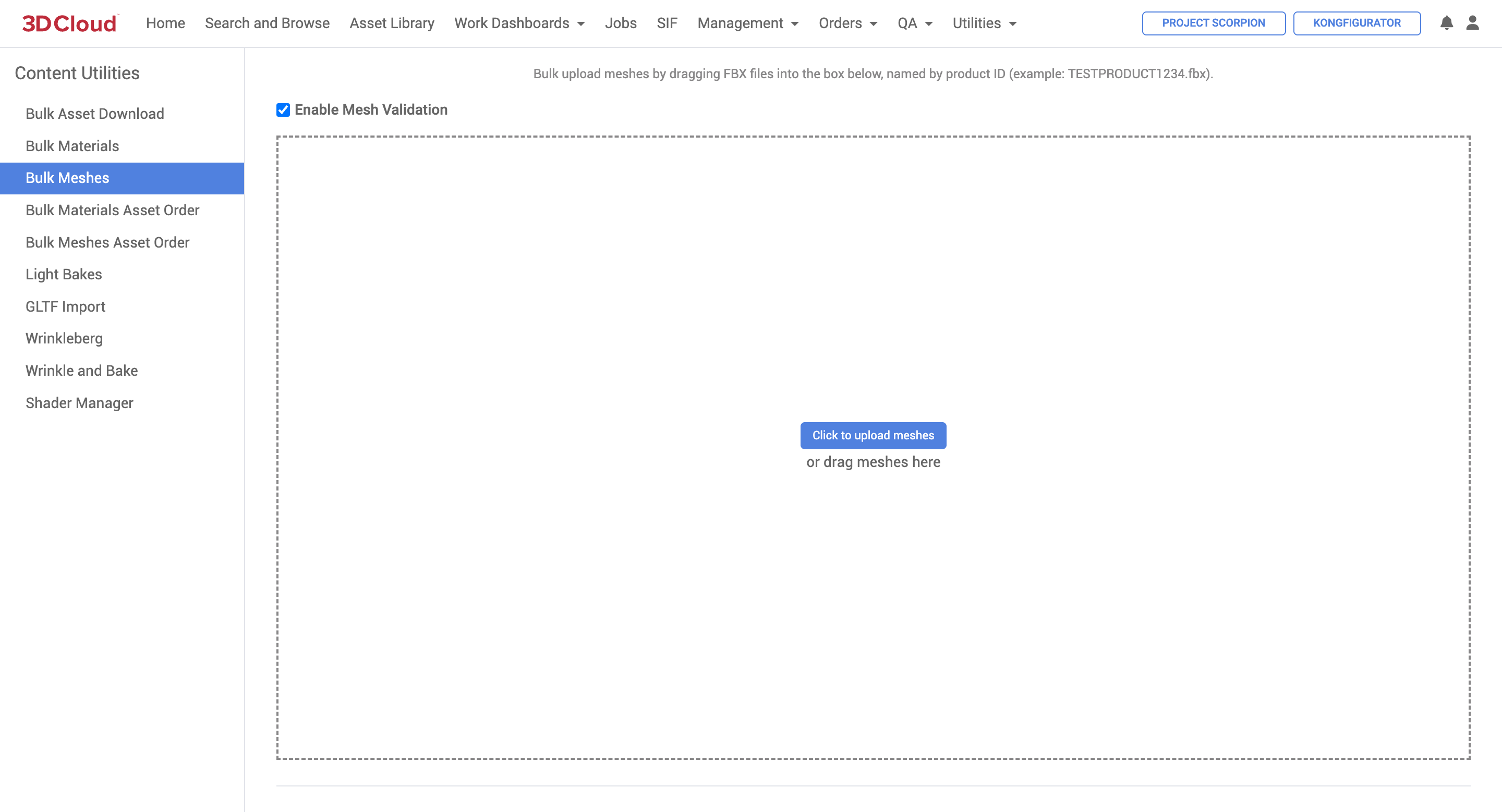
When uploading meshes, they must be named by Product ID (example: if the Product ID is “TESTPRODUCT1234” then the file name would be: TESTPRODUCT1234.fbx. You can either drag the files into the dotted box or click “Click to upload meshes” and navigate to the mesh files.
When the meshes are processing, they will appear in the “queue”. While there is content still in progress, you cannot “Clear Queue”. It might take a few seconds for the time estimate to update, but the progress will show with a loading bar (like on the “Jobs” page). You can always add more mesh files and they will be added to the queue.
Note: There is a limit of 15 meshes processing simultaneously, any mesh after the 15th will be queued and startup after another mesh finishes.
While this content is processing, we recommend if you are planning on working on other tasks in 3DC, use a new tab or window of 3DC. If you try to leave this page or go to another content tool, a “Jobs are still processing…” message will appear. We recommend clicking “No” so you can see if any jobs fail and track progress. However, all content processing jobs will show up under Jobs → Asset Conversion. (Time remaining might be ~5-20 seconds off between the loading bar on the jobs page vs. the bulk mesh tool queue but should be relatively in sync).
To view the “Parameters” of the job, you can hover over the job you want to view, and click the “Tool” icon. The parameters can currently only be viewed through the Jobs page.
When the job completes, on the Jobs → Asset Conversion page you will see something like this:
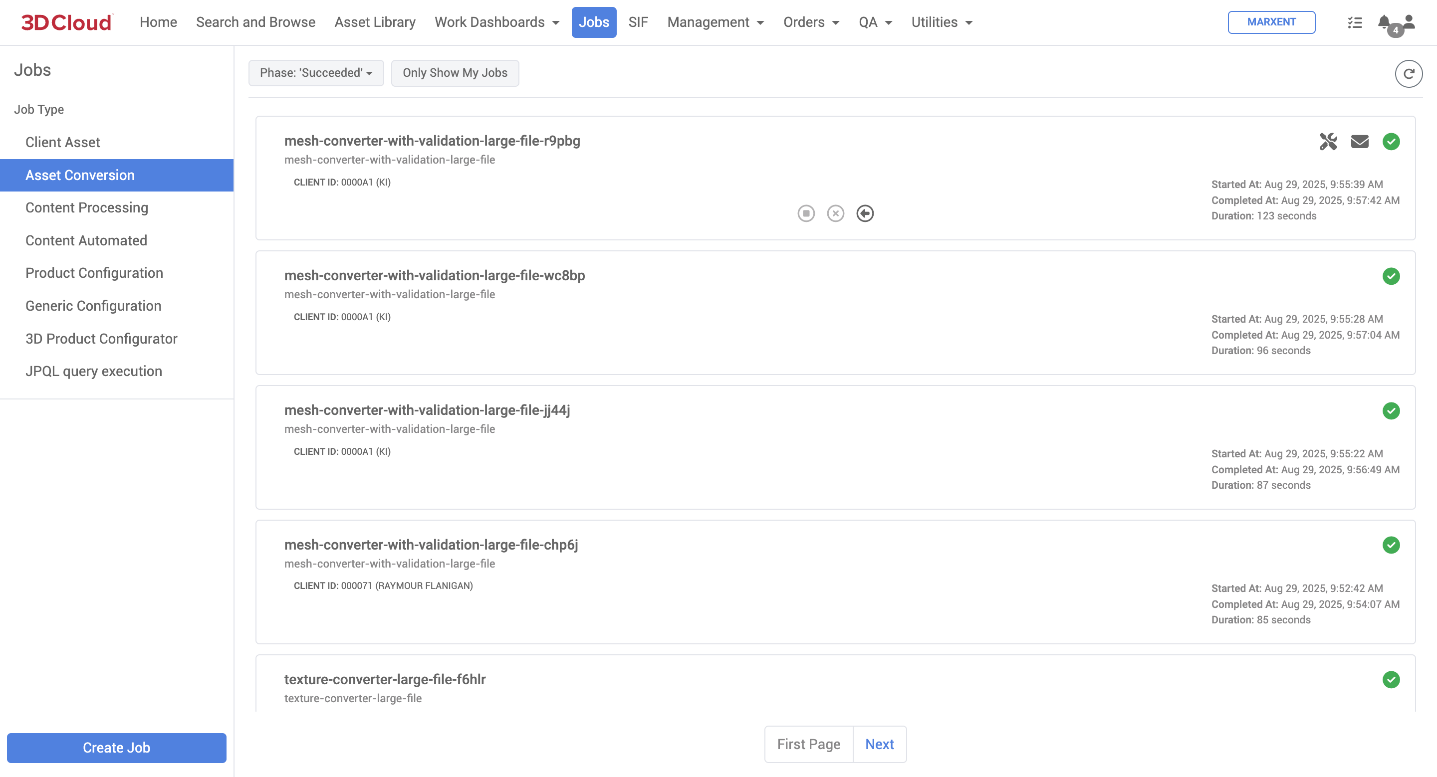
If a job fails, there will be a red “!” icon. The envelope icon will list any valid errors the job ran into. If there are no errors listed (a bug we are working to resolve), click the arrow button to retry the job. We typically see success after retry.
Bulk Materials Asset Order
The Bulk Materials Asset Order content utility allows the bulk upload of textures. Textures must be in a specified directory structure as follows:
Batch Directory / Material VCN / textureName_textureTypeLetter.tga
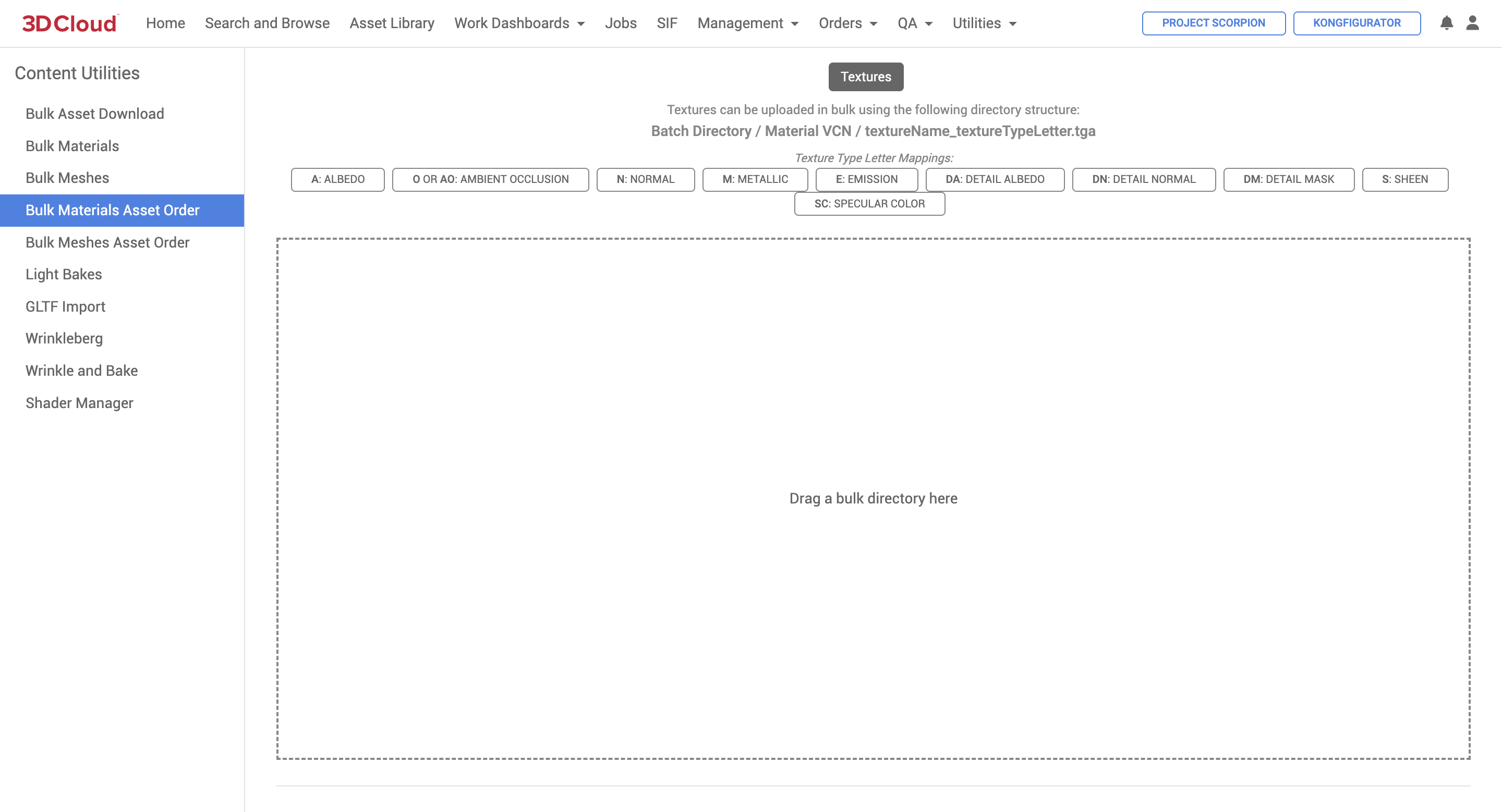
Bulk Meshes Asset Order
The Bulk Meshes Asset Order content utility allows the bulk upload of meshes as .fbx files, which should be named with the following file name convention:
vcn-mes-000001-00000001.fbx
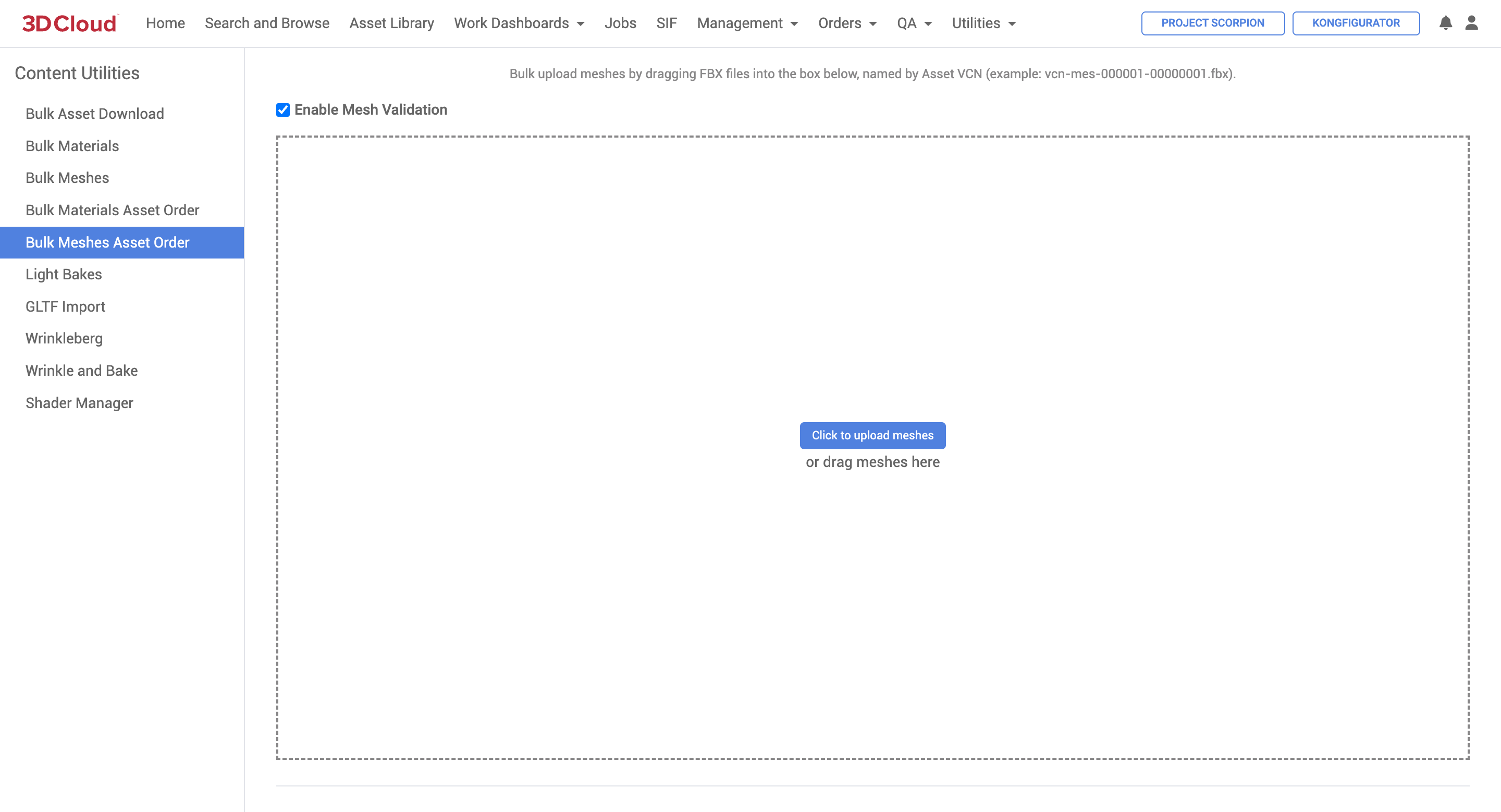
Light Bakes
The Light Bakes content utility is used to generate texture maps (like Ambient Occlusion) from meshes to add material detail that improves the realistic appearance of 3D products in our application viewers.
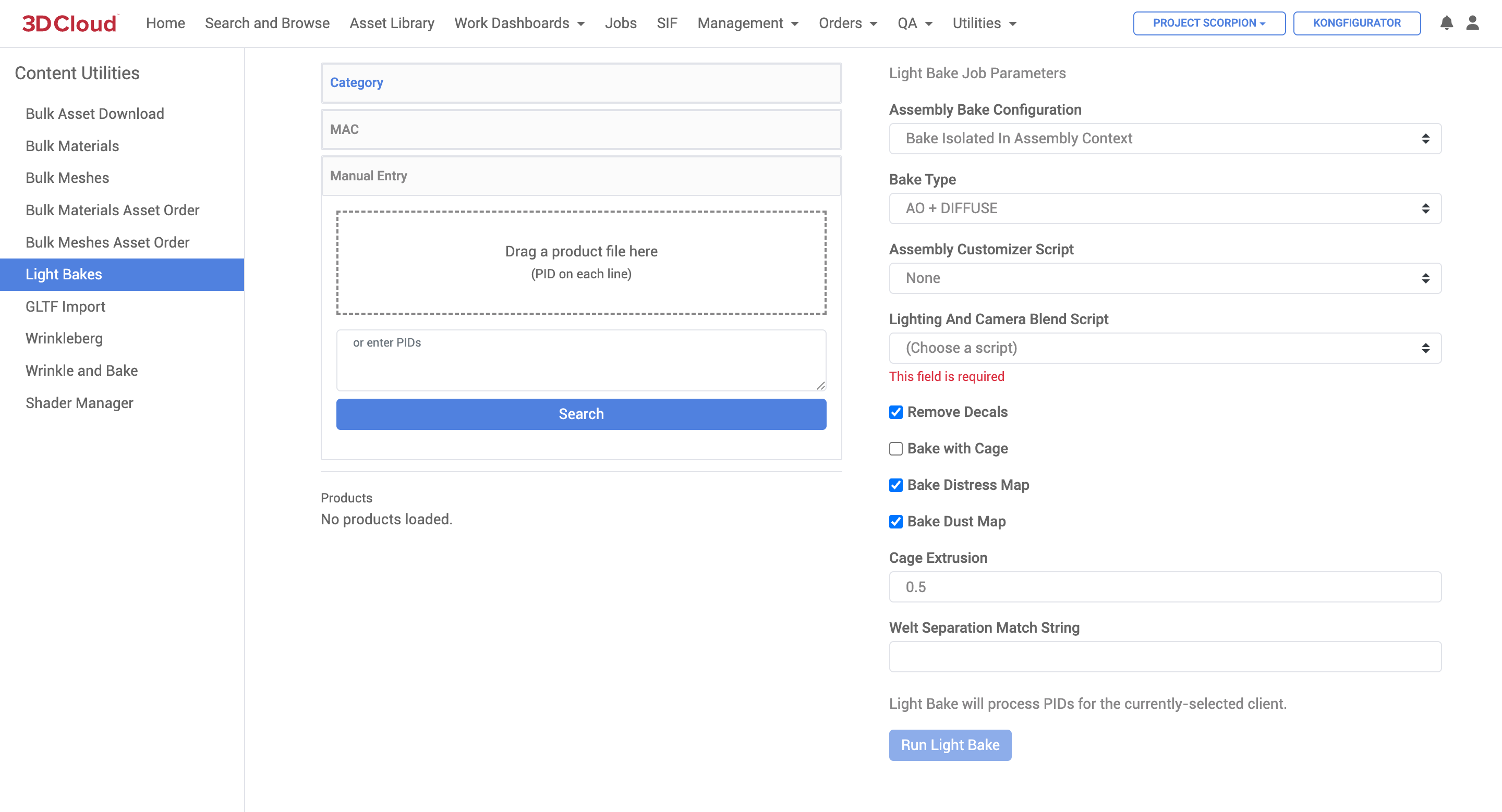
|
|
3D product real-time view (without Light Baking) | 3D product real-time view (with Light Baking) |
To run a light bake you must have the following:
A Product (PID)
The Product must have a Mesh
All Virtual Product Materials must have a Material assigned
How to Bake
Here are the steps to take when running a light bake:
Enter one or many product IDs you would like to bake. Note: All products receive the same light bake settings
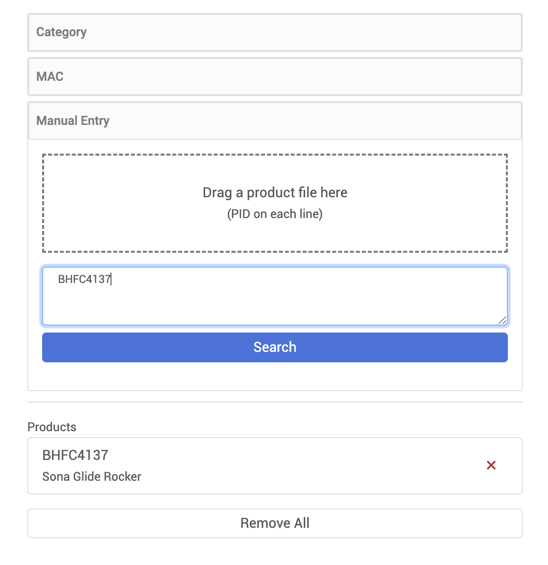
Configure the light bake parameters as desired. See the Parameters section below for a list and details description of each.
Note: All default parameters will run a bake out of the box
Select Run Light Bake at the bottom of the parameters to execute the job.
Note: The job will automatically upload the appropriate light bake textures to the product and assembly product materials.
Light Bake Parameters
Name | Description |
|---|---|
Generate Ground Blob Shadow | Generate a floor plane and bake out a shadow blob? If |
Ignore Assembly | This setting only applies to PIDs in the PIDs List that do NOT have an |
Ground Blob Shadow Override To Use AO | Have the shadow blob ignore the |
Ground Blob Shadow Padding | The extra padding to add to the size of the plane to cover the entire shadow cast on the floor (within reason). |
UV Seams Padding | The number of layers of padding around the UV seams |
Cycles Sample Count | Number of samples to render for each texel (aka UV vertex coordinates) |
Vignette Image | The image used to fade out the ground shadow at the edges of the ground plane. With 100% white at the edges and 100% black in the center. |
Bake Type | In Blender, this is the setting at Valid Bake Type Values: (choose only 1): AO or DIFFUSE Valid Lighting/Contributions values (choose multiple, or choose none, separated with a comma): DIRECT and/or INDIRECT If you choose AO, only an AO Texture is generated. If you choose DIFFUSE, only the diffuse (Emission/LM) Texture is generated. If you choose AO + DIFFUSE, both Textures are generated. |
Pass Filters | In Blender, this is the setting at Valid Bake Type Values: (choose only 1): AO or DIFFUSE Valid Lighting/Contributions values (choose multiple, or choose none, separated with a comma): DIRECT and/or INDIRECT |
Auto Detect Pre Existing Assembly Blob PIDs | If set to `TRUE`, all the PIDs in the |
Load Materials | When set to |
Output Resolution | The output resolution to save to disk. This must be in the format Note: if a |
Bake Resolution | The resolution to calculate the bake at. This image is only stored in memory, see the |
Assembly Customizer Script | An (optional) user Python script used to automate customizations to the loaded assembly. See the |
Bake Distress Map | Bakes a Distress Map and encodes it into the AO texture |
Bake Dust Map | Bakes a Dust Map and encodes it into the AO texture |
Remove Stiches | Removes stitches before baking |
Model Version To Download |
|
Texture Version To Download |
|
GLTF Import
The GLTF Import content utility enables users to import glb or gltf files into the 3D Cloud AMS, converting them into vcn-mes files and 3D Cloud materials with texture maps. This utility facilitates easier onboarding of clients who have existing assets in the glb or gltf format.
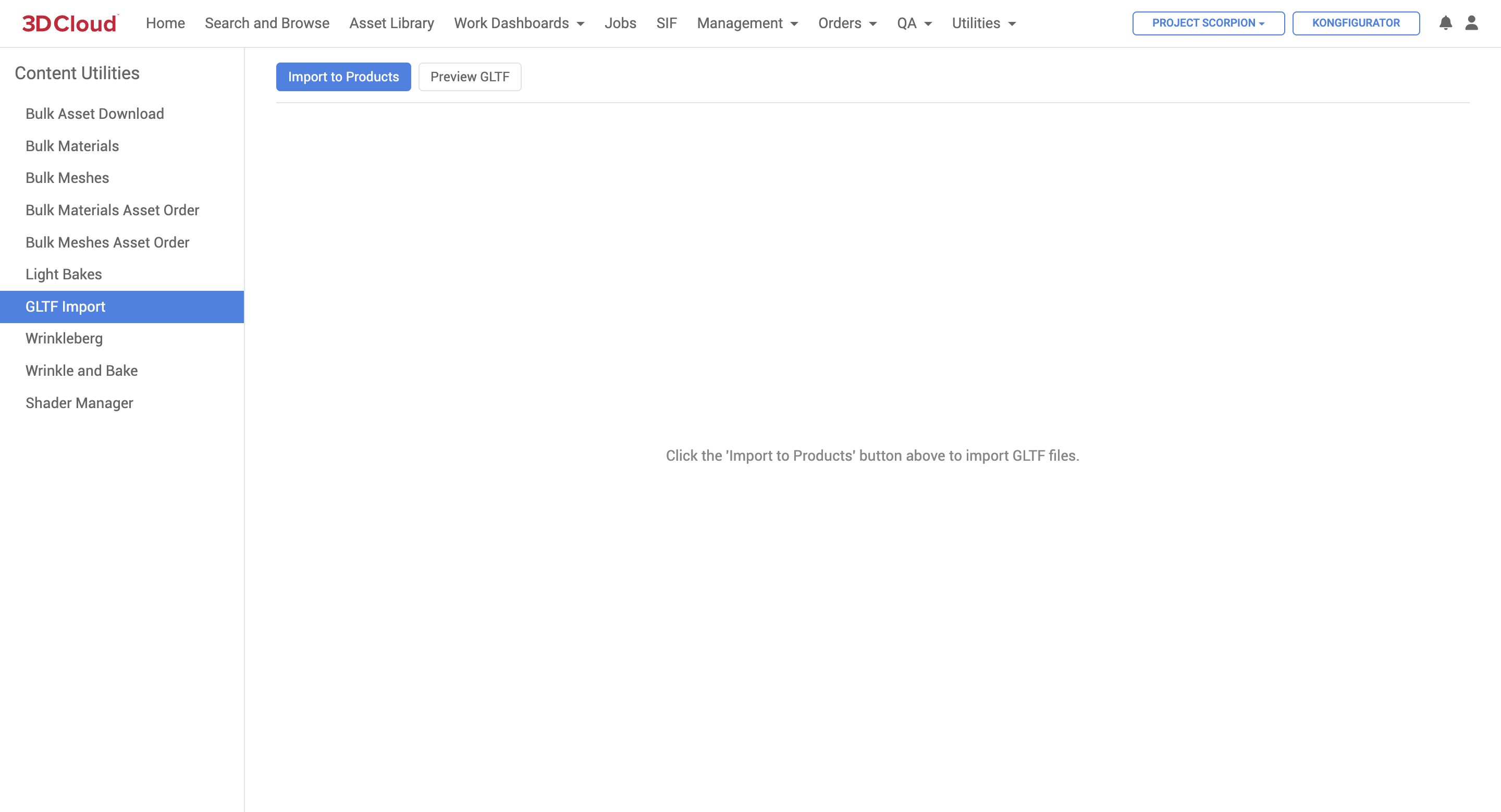
There are two main actions in this utility.
Import to Products
The tool that enables the import of a sheet-based list of product data and accompanying glb assets.Preview GLTF
A real-time 3D viewer tool to preview existing glb files using drag and drop.Native Viewer
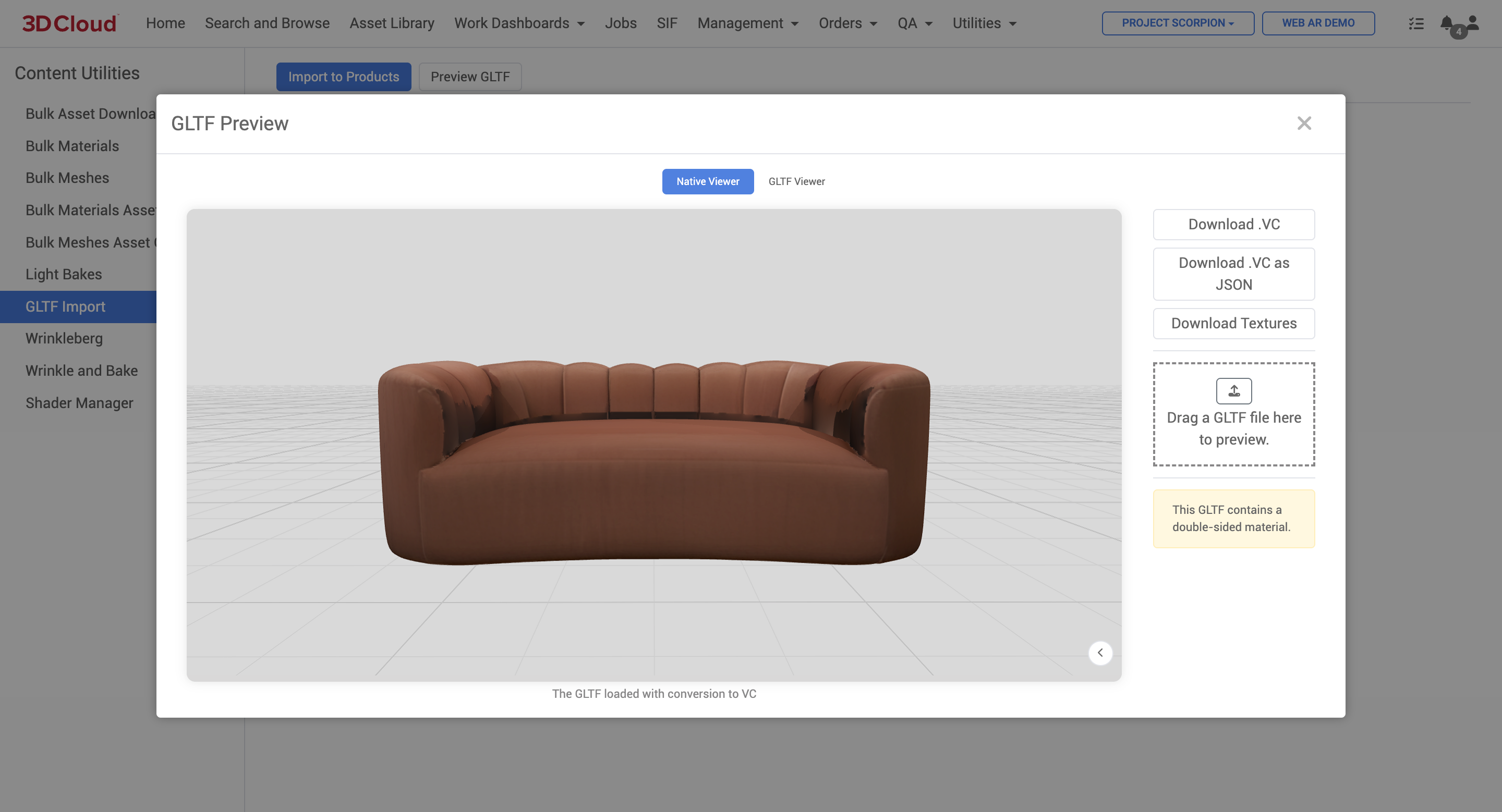
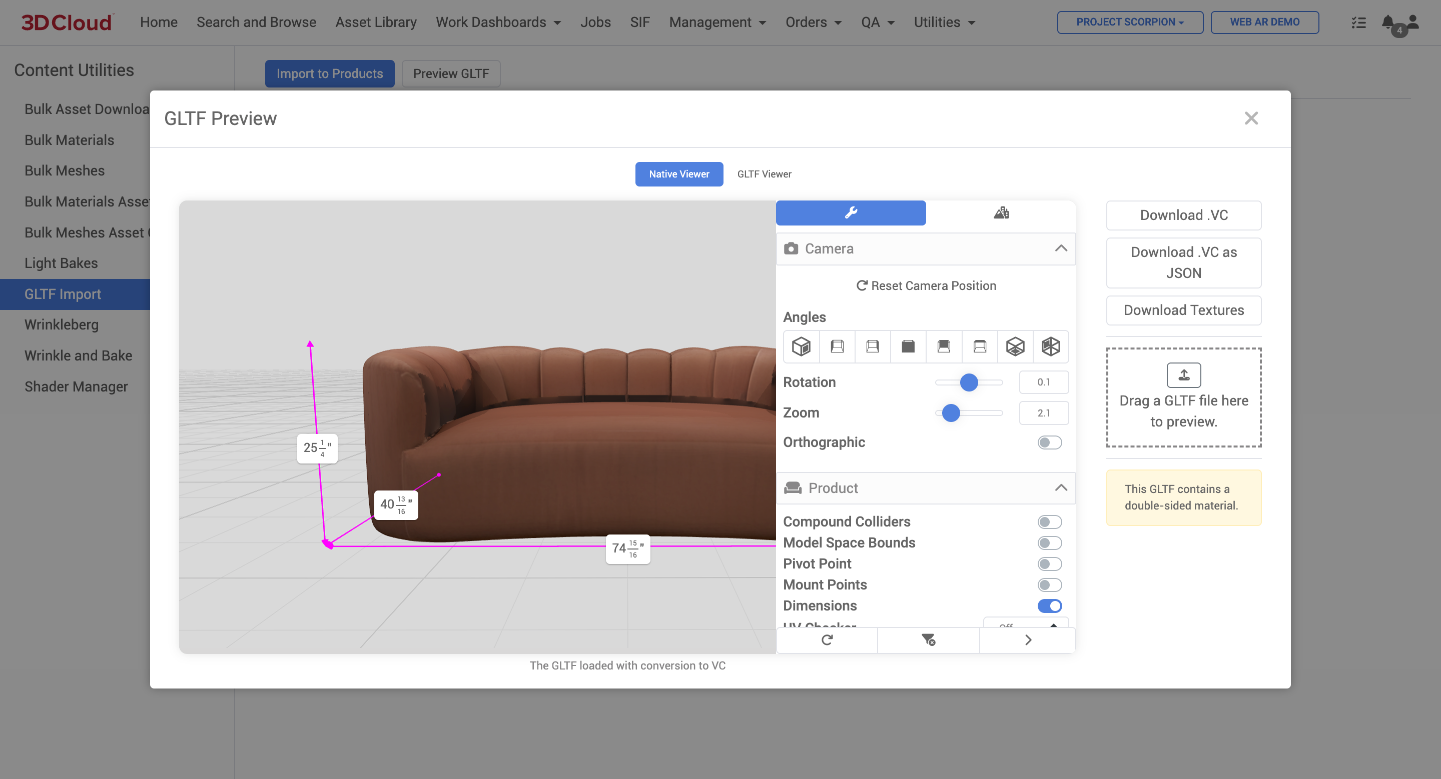
On the Native Viewer mode you can do the following actions:
Inspect the asset with our native product viewer controls.
Download VC
Downloads a VC file and metadata JSON file for the glb asset.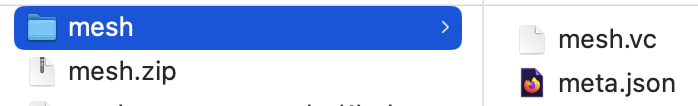
A .vc file is a proprietary 3D model file format used by 3D Cloud. It is designed to house all the component parts of a model in a relational database, allowing for efficient reuse of components like shared materials across assets. This format is particularly useful for models with many variants and is optimized for frame rate and qualityThe .vc file format supports embedding business rules into products, enabling them to interact in virtual spaces, such as assemblies and mount points. It is used across various platforms and is preferred over other formats like USDZ for its flexibility and support for advanced features.
Download VC as JSON
Downloads the JSON version of the .vc file.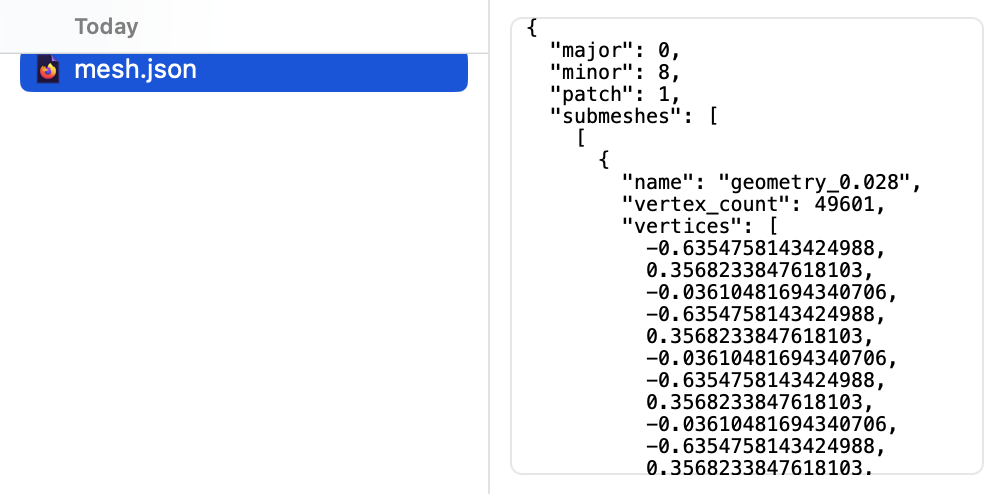
Download Textures
Downloads the baked texture file and JSON for the glb asset.
GLTF Viewer
A standard Babylon.js viewer without our native controls is also an option on this tool.
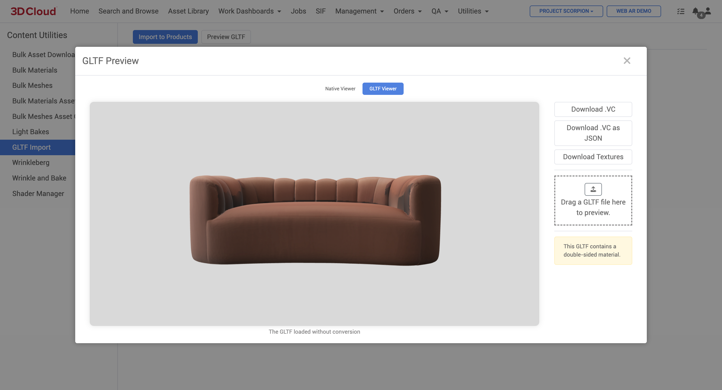
How to Upload a Batch of GLB Files
Import a Product Import sheet first to create the virtual products in the AMS first. Products (PIDs) must already exist in the AMS before importing glb files.
Click on the “Import to Products” button to upload a sheet.
.png)
2. The GLTF Import modal window provides an example product sheet, or you may edit the sheet in the window (not recommended for many glbs to import). Click the “Download an example product sheet here.” link to download an .xlsx template.
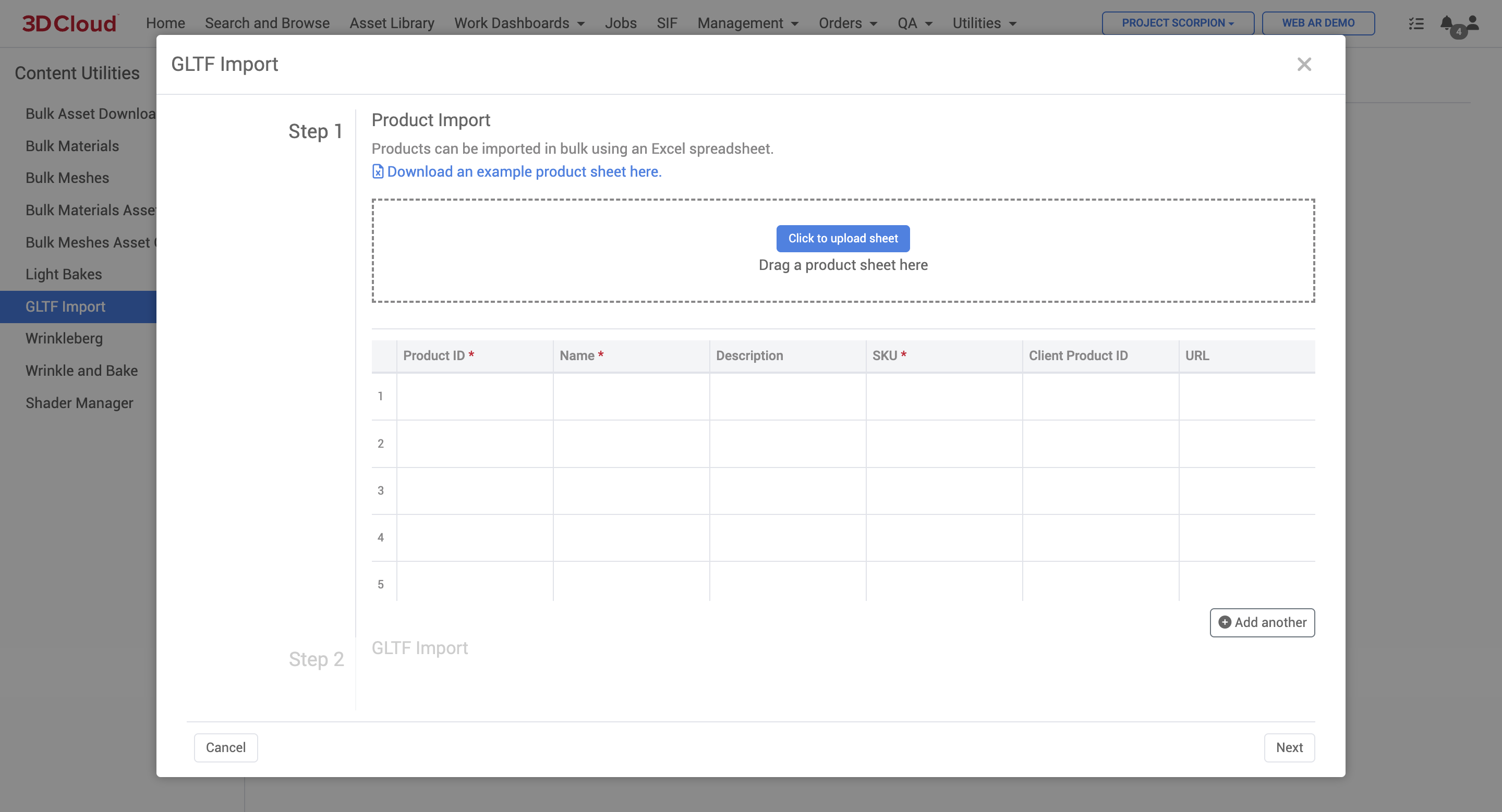
3. Edit the sheet to add the products you want to create, and save out an .xlsx file for upload.
.png)
Sample glb Import Sheet
Note: The required columns on this sheet template are Product ID, Name, SKU, Dimensions (in meters), MFR SKU/Item #, and MFR Name.
Also, the Dimensions column on the sheet is expected to be express in METERS. So when entering the WxDxH values as shown in the example, be sure to convert dimensions to these units. (1 inch = 0.0254 meters) before importing the sheet. Units can be verified after the import.
4. Correct any errors on your sheet after it is validated by the system.
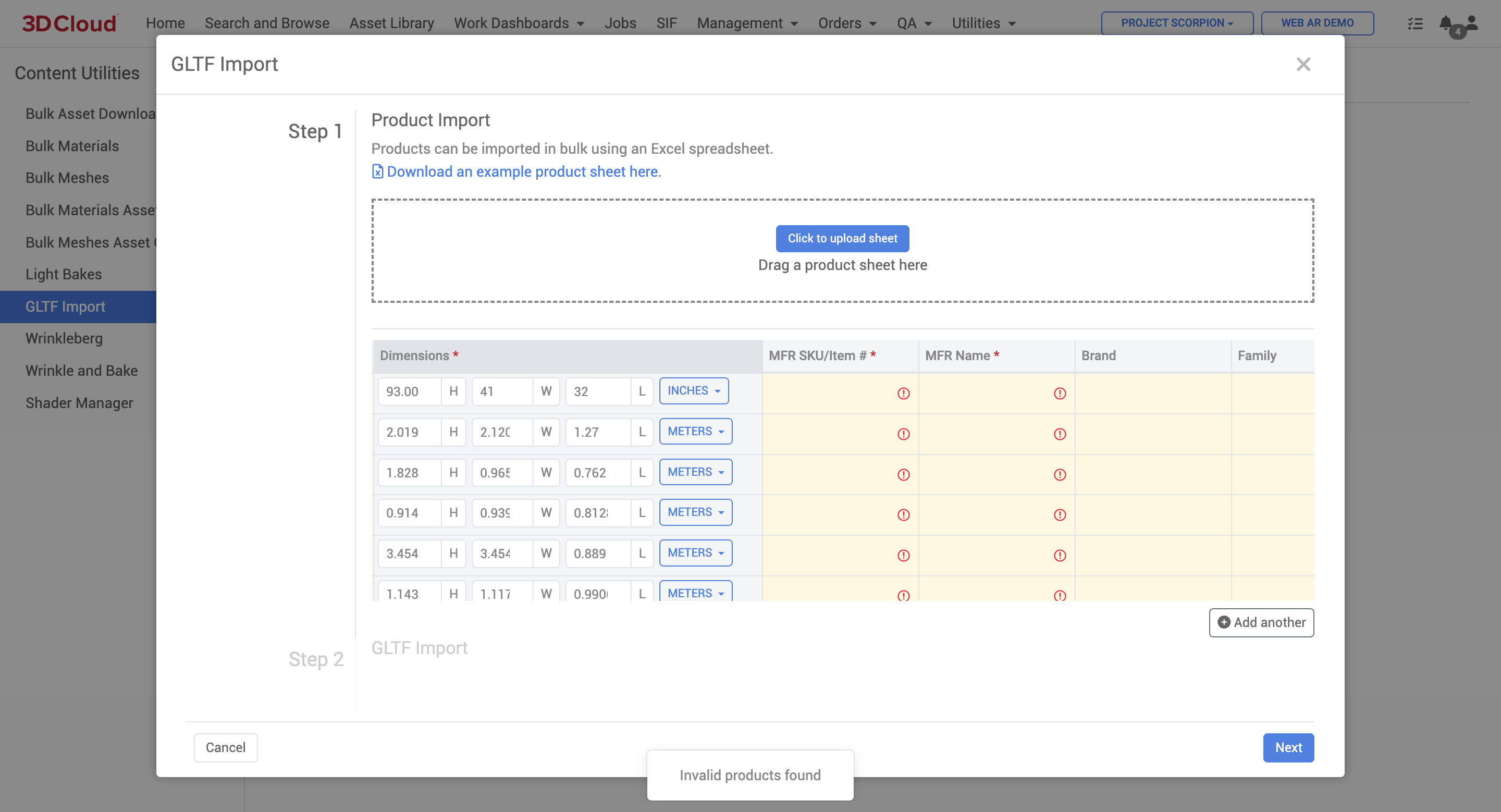
Error: Invalid products found because there is missing required columns
5. Click the “Click to upload sheet” button and select your .xlsx file to upload, or drag the file onto the dotted upload box area.
.png)
Product Import window after sheet is uploaded
Now you’ll need to upload the glb asset for each product in the list. For smaller numbers of glb imports, you can choose to click the “Upload” icon (looks like a hard drive with an up arrow) on the last column of the window list and repeat for each product.
For large volumes of glb assets, click the “Next” button on the lower right to proceed to the GLTF Import Step 2, which will accept a large batch of files simultaneously, as long as the .glb files are named to match the SKU in the product list. (i.e. sku12345xyz.glb). Drag and drop your files into the dotted input box area.
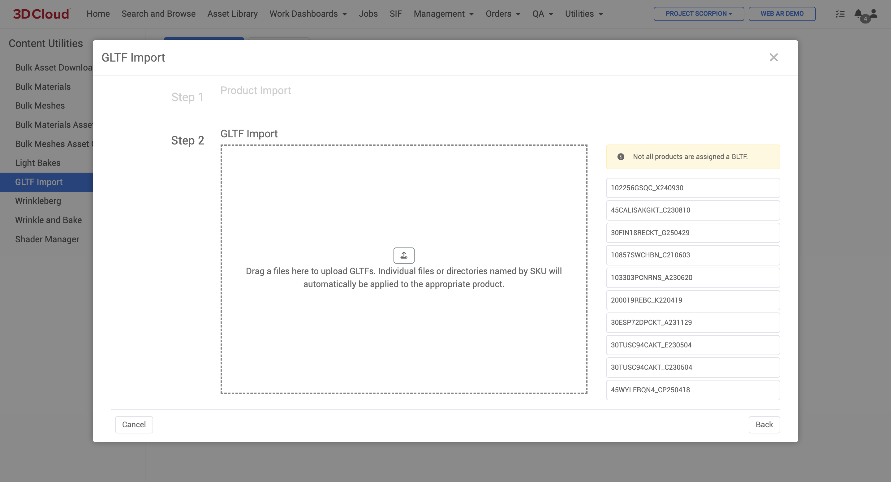
If your glb files are named to match the SKUs, you will see a success message, “All products have been assigned a GLTF Import to create products and assets.”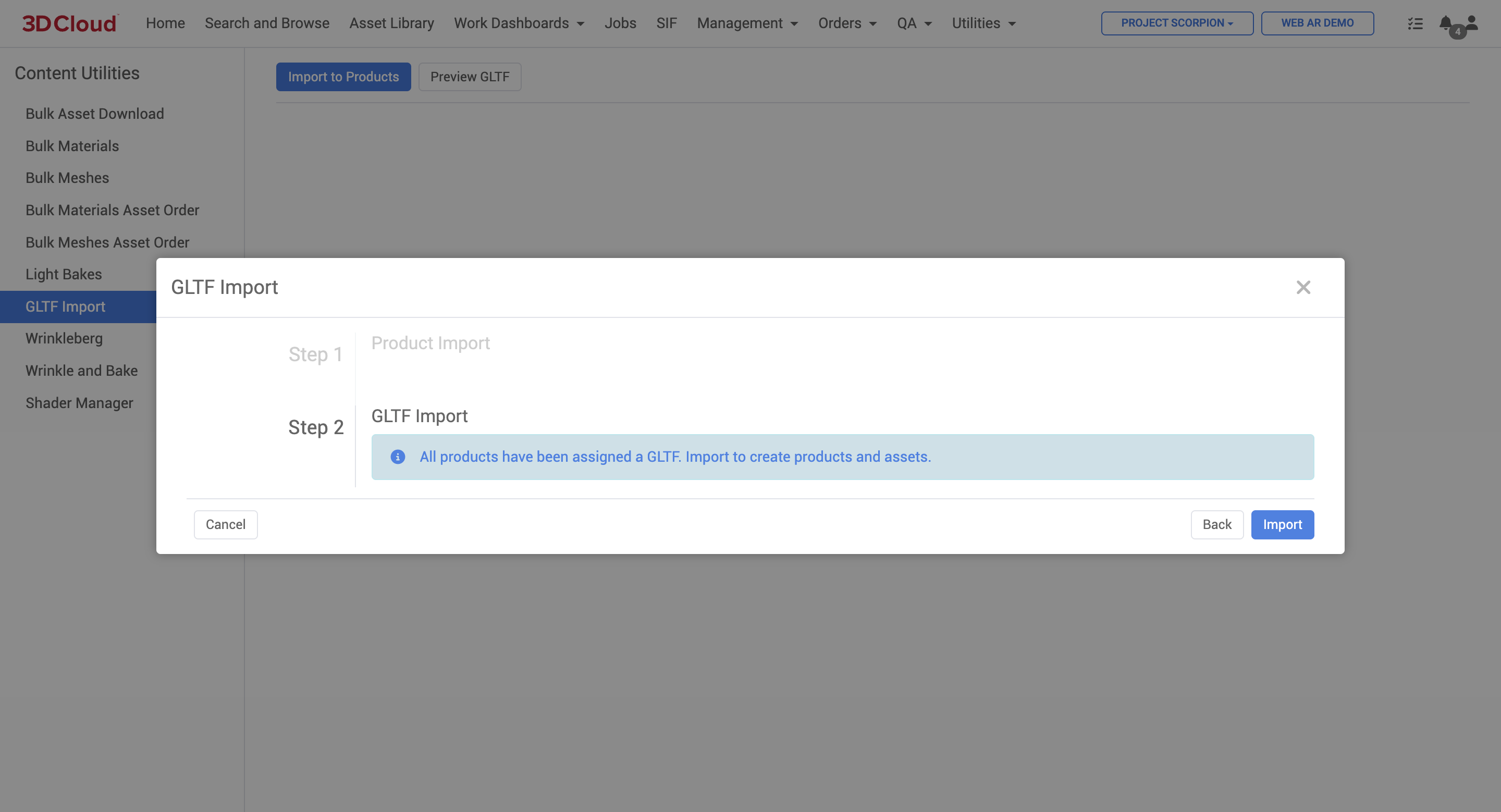
Click the blue “Import” button to proceed with the import.
A progress page will be displayed while the assets are being ingested and the virtual products are being created on the system..png)
When the import process is completed, you will see a “Complete” message on each product.
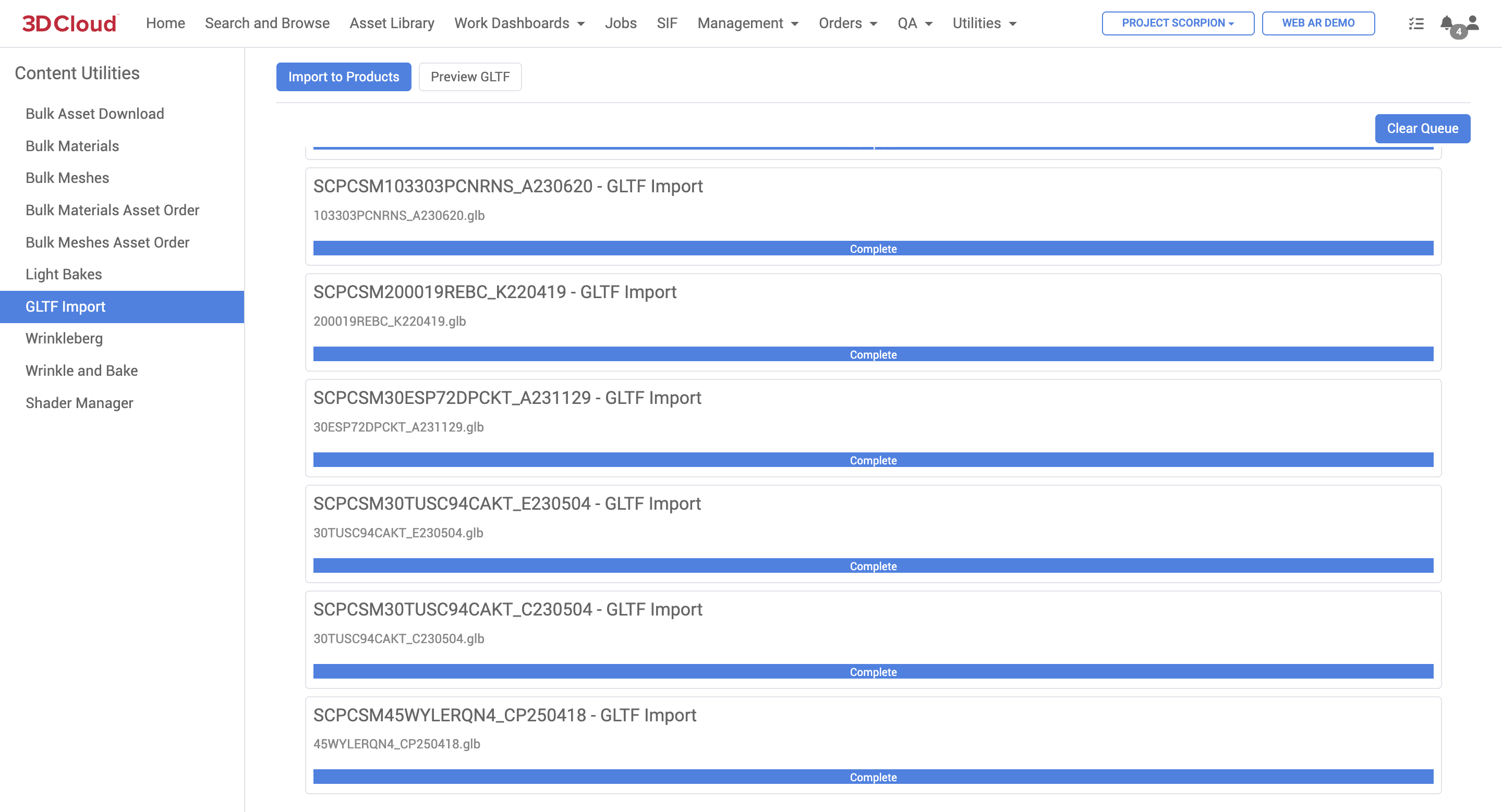
You can then use Search and Browse to verify that your products are created and the meshes load in the product detail pages. Your products and glb files are now ready to be using in applications.
.png)
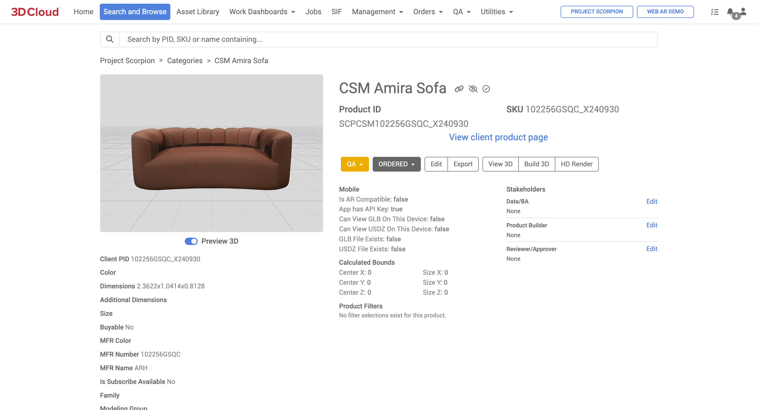
Wrinkleberg
The Wrinkleberg content utility is used to batch create wrinkles in meshes for greater realism. (“Wrinkleberg'“ is just the affectionate 3D Cloud name for the feature, and is accessible via Utilities → Content → Wrinkleberg. To specify a job, the user can browse to find Product IDs (PID) upload a list (one PID per line), or enter PIDs directly into the form.
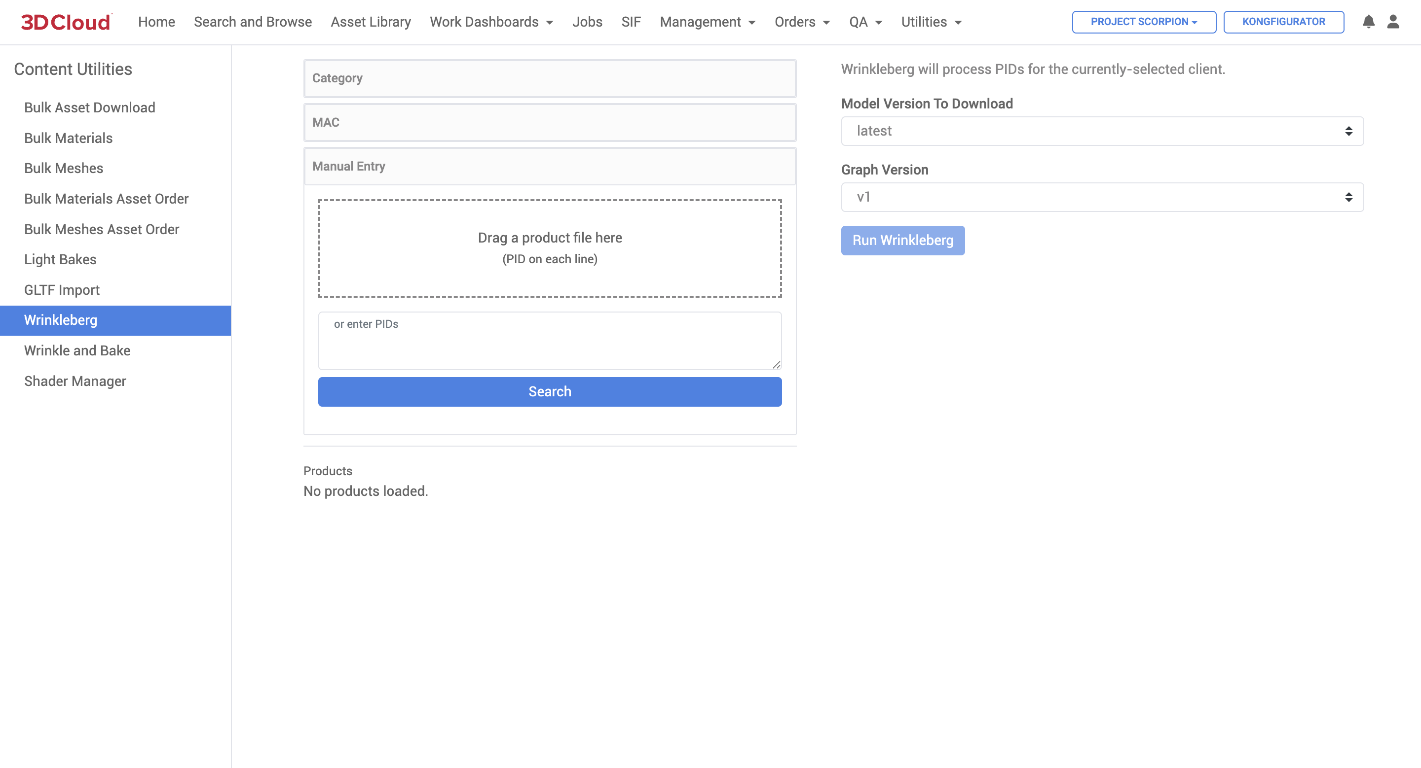
Wrinkleberg will run on a single product and will generate either one or two object space maps on the object space material of the mesh asset. Products without material tags triggering wrinkles will only get an Occlusion map created. Products with material tags triggering wrinkles will get an Occlusion map and a Normals map. Both maps will contain wrinkle information.
Wrinkleberg should not be requested for products using sculpted mesh assets. Those products should instead be placed in an OS creation ticket that specifically requests Bake Boss. This is because studios will either model all wrinkle detail into the mesh, or they will provide their own Normal map for sculpted meshes (to embed high-poly detail into low-poly assets).
Wrinkleberg also does not consider assembled products when creating OS maps. If your Product has other products assembled with it that need to be considered for Occlusion, please specify this in the OS ticket so we know to run Bake Boss after Wrinkleberg.
“Bake Boss” is usually used after Wrinkleberg (when requested) to create an Occlusion map that considers multiple products during the baking. This is mostly used for single items made up of both common and configurable parts (office chairs are a good example). With products being used in Kongfigurator, configuration logic can be used to drive the Occlusion map creation by Bake Boss, so it’s very beneficial to have that logic set up before requesting a bake. Please include the config ID in the OS Jira ticket.
Bake Boss can also be requested if the quality of the Occlusion map generated by Wrinkleberg is not sufficient for your use-case, or if your product requires light maps or emission maps to be created.
Wrinkle and Bake
The Wrinkle and Bake content utility is accessible via Utilities → Content → Wrinkle and Bake. This tool is used to generate texture maps (like ambient occlusion) from meshes for additional material detail.
.png)
A list of one or many Product IDs is entered into the form for a Wrinkle and Bake job, and job parameters are selected based on the specific bake type, lighting and camera settings desired. The “Run Wrinkle and Bake” button submits the job request.
Typically Wrinkle and Bake jobs are submitted by an internal 3D Cloud Studio Lead, who are trained in the proper parameters for each job. Contact your 3D Cloud Account Manager for details.
Shader Manager
The Shader Manager content utility is used to manage shader data that materials need to reference. It can be used by various applications to handle render specific shaders for Advanced Materials. The utility is accessible at Utilities → Content Utilities → Shader Manager.
The target of this functionality is to support microfibers like Suede and Velvet, but can support various other situations where a custom shader is required.
Access Requirements
In the AMS administrative Feature Manager area, a required Feature called “Shader Manager (3DC)” needs to be set for the User Role in order to access this tool in the 3D Cloud AMS. The feature contains a User Role Permission for SHADER_VARIANT set to Create, Read, Update and Delete.
.png)
Usage
On the left column of the Shader Manager page you will see a list of all existing shaders. The right side shows the options to configure the shader and its metadata.
Create a New Shader
Click the Create New Shader button to create a new shader. This will clear out the form from any previously selected shaders.
Update an Existing Shader
You can update existing shaders by selecting them on the left hand pane.
The form will populate with the existing values. Make your desired adjustment as Save the shader.
After you save, this will increment the version and preserve previous data.
Shader Versions
Versioning shaders has the advantage of preserving previous data while having the capability to create and experiment on new data.
After you make edits to an existing shader and save, a new version of the shader is created.
It is important to note that any materials that have an existing version of that shader assigned will not automatically get the new version. These materials will need to be identified and increment accordingly.
Assigning a Shader to a Material
You can assign a shader to a material from either the Material Editor or Product Builder pages.
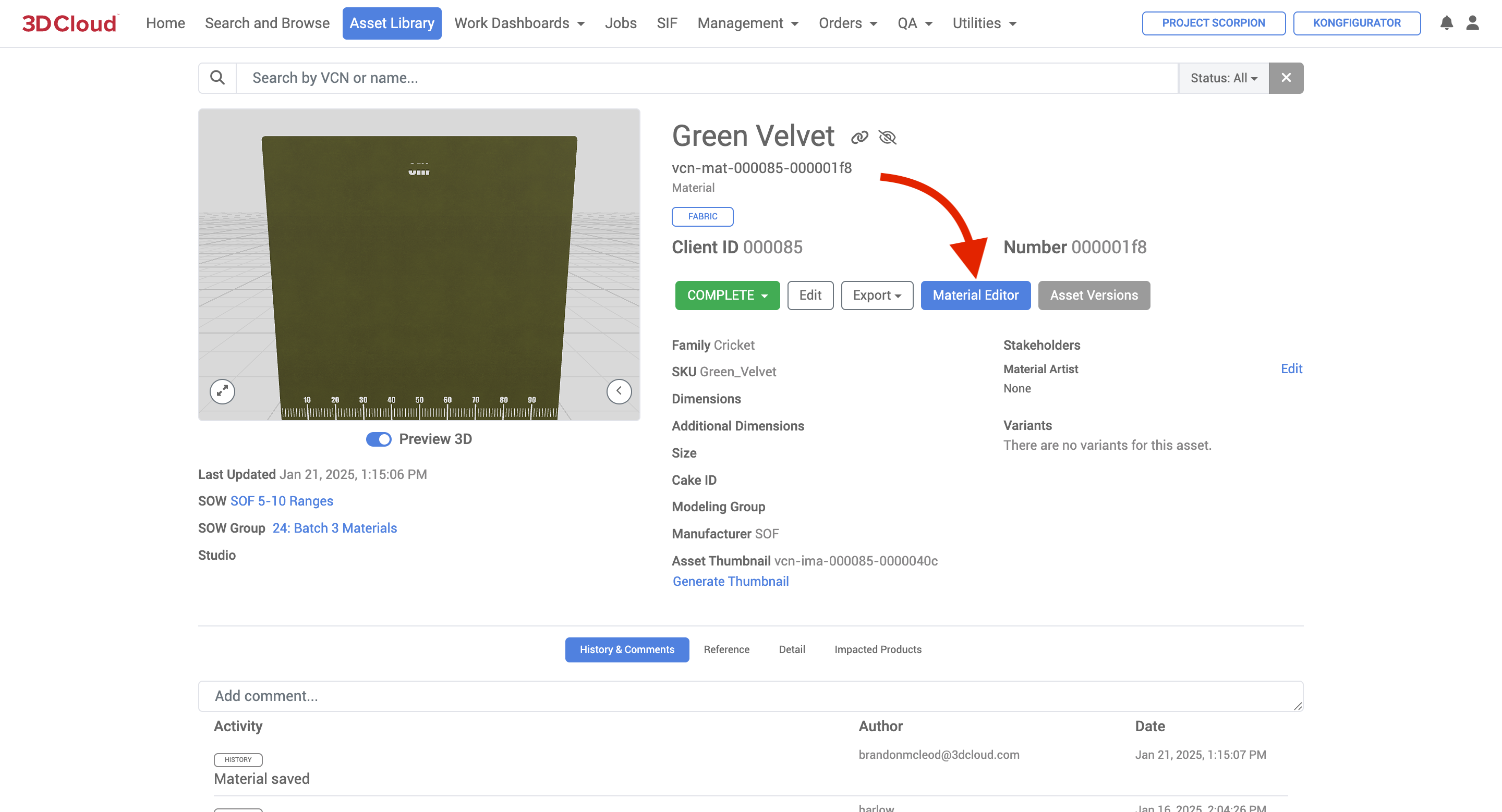
Select the desired material
Go to the Misc Tab
Find the dropdown for Shader
Select the desired Shader
Click the “Save” button on the upper right
.png)
Note: By setting the shader to (None), it will un-assign the shader and automatically delete the Material Property after saving the changes.
Material Properties
After assigning a shader to a material, new properties get generated. These get assigned to the material_property table.
Name | Value | Type |
|---|---|---|
BlenderShaderId | The shader’s unique id | string |
BlenderShaderUrl | The CDN url to the shader data. This later gets used by consumers to easily reference the data (like the blender render server) | url |
BlenderShaderVersion | The desired shader version to use for this material | integer |
Note: Additional support will need to be added for other backend systems that need similar functionality down the road. Right now, we only support Blender. Other software will need their own entries (Babylon, Cycles, RenderMan, etc…)
Fabric by the Yard Tool
The Fabric By the Yard Tool is a client-specific application that lives in the 3D Cloud AMS (must have permissions to view) under Utilities → Fabric By the Yard Tool. The tool was created so that client users can independently update specific data points for the various fabrics assets they own. We then use the data to calculate how much fabric is required to create custom upholstered products.
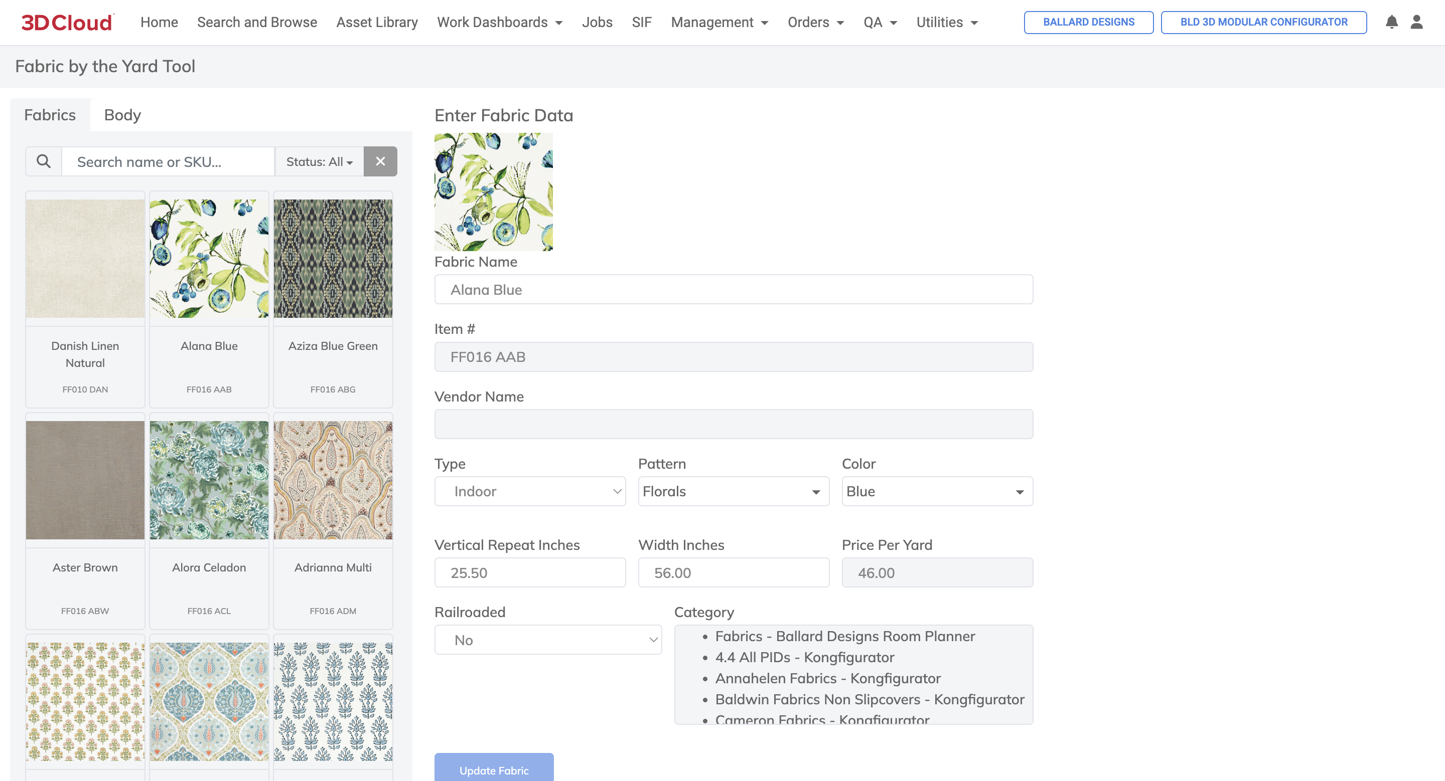
How to use the Tool
Search for your Fabric by SKU under the Fabrics tab
Search for your Body by SKU under the Body tab
View the Vertical Repeat Inches field under the Fabrics tab for the selected fabric
View the Railroaded Yes - or - No field under the Fabric tab for the selected fabric
Now navigate to the Body tab and in the yardage chart at the bottom, find the Vertical Repeat Inches amount from Step 3 in the header row of the yardage chart
Find which row corresponds to the fabric’s railroad status - yes or no
The final number is the yardage required to cover the body
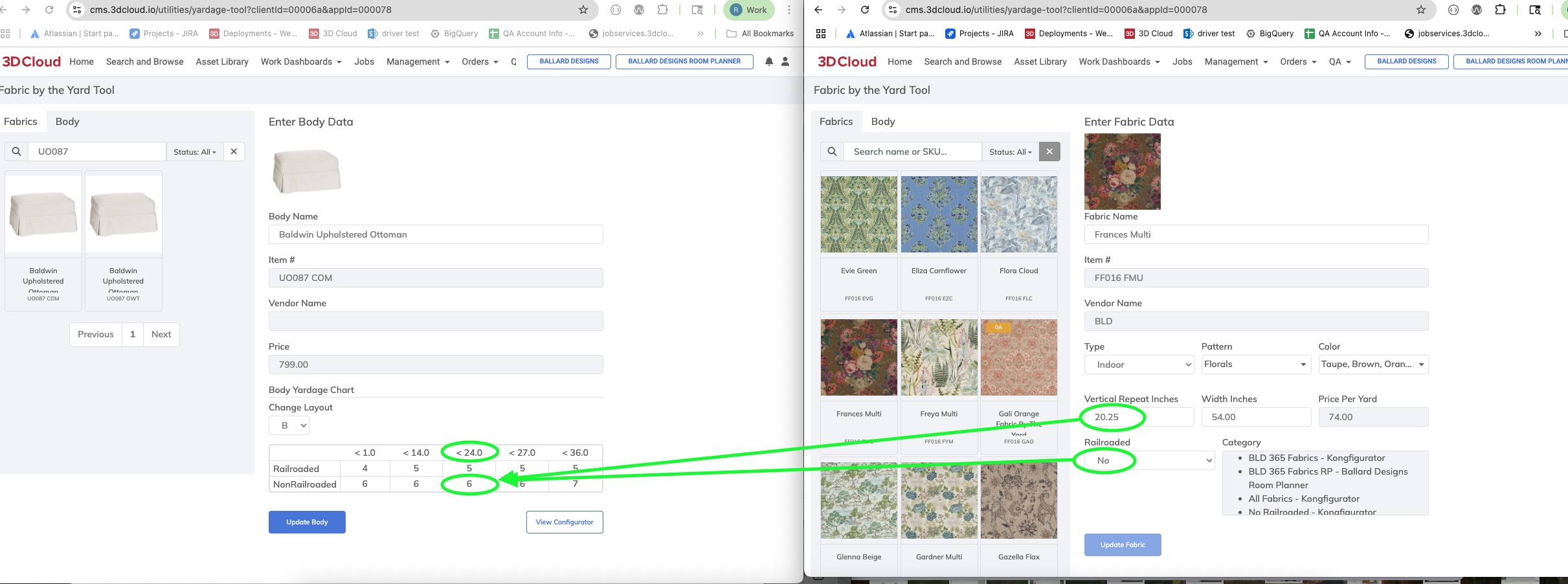
Example: Baldwin Upholstered Ottoman (SKU: UO087 COM) with Frances Multi fabric (sku: FF016 FMU) = 6 yards
8. To determine a product’s price:
Body Price + Fabric Price x Yardage = Total
Example: Baldwin Upholstered Ottoman (sku: UO087 COM) = $799
with Frances Multi fabric (sku: FF016 FMU) = $74/yd
x 6 yards = $1243 Total
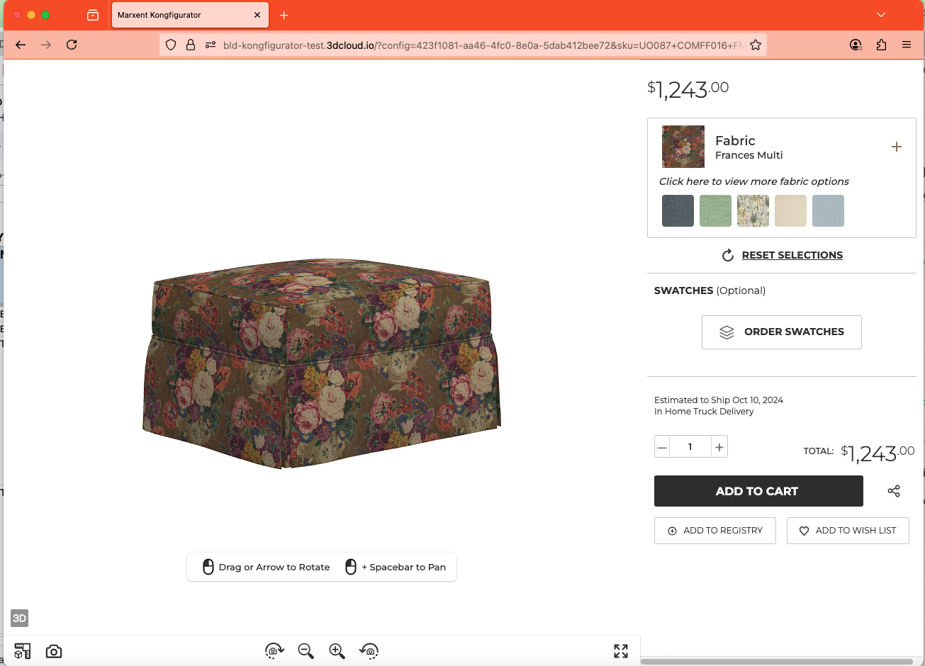
Feedback
The Feedback Utility is a tool used to view feedback submitted from frontend applications to the User Service. It is accessible under Utilities → Feedback and allows users to search and sort feedback based on specific criteria such as date range. Users can export the feedback data to a spreadsheet and navigate through results using pagination if necessary.
The feedback data collected includes:
Description: The main feedback provided by the user (Text)
Feedback Type: Optional categorization such as Feature Request, Product List, or Support Request. (Text)
User Type: Optional categorization such as Associate or Customer. (Text)
Timestamp: The date and time when the feedback was submitted. (Timestamp, e.g. 2021-05020 18:21:02)
Data: Additional parameters sent with the feedback request in JSON format
Usage
The functionality for this utility is fairly straight forward. You have various options for searching and sorting.
Enter the Start Date and End Date for the feedback you are searching for. Then click
Search.The results will display on the page if any feedback was found within that date range.
You can export the data to a spreadsheet using the download/export icon to the right of the Search button
If there are many results found, pagination will be presented at the bottom of the page
Inspiration Filters
The 3D Cloud AMS Inspiration Filters utility provide a navigation structure for inspiration heroes. The tree structure is as follows:
Inspiration Filter → Inspiration Filter Option → Inspiration Hero
Note: The inspiration filters page can also be accessed by navigation through the client application menu structure to a SHOWROOM typed menu.
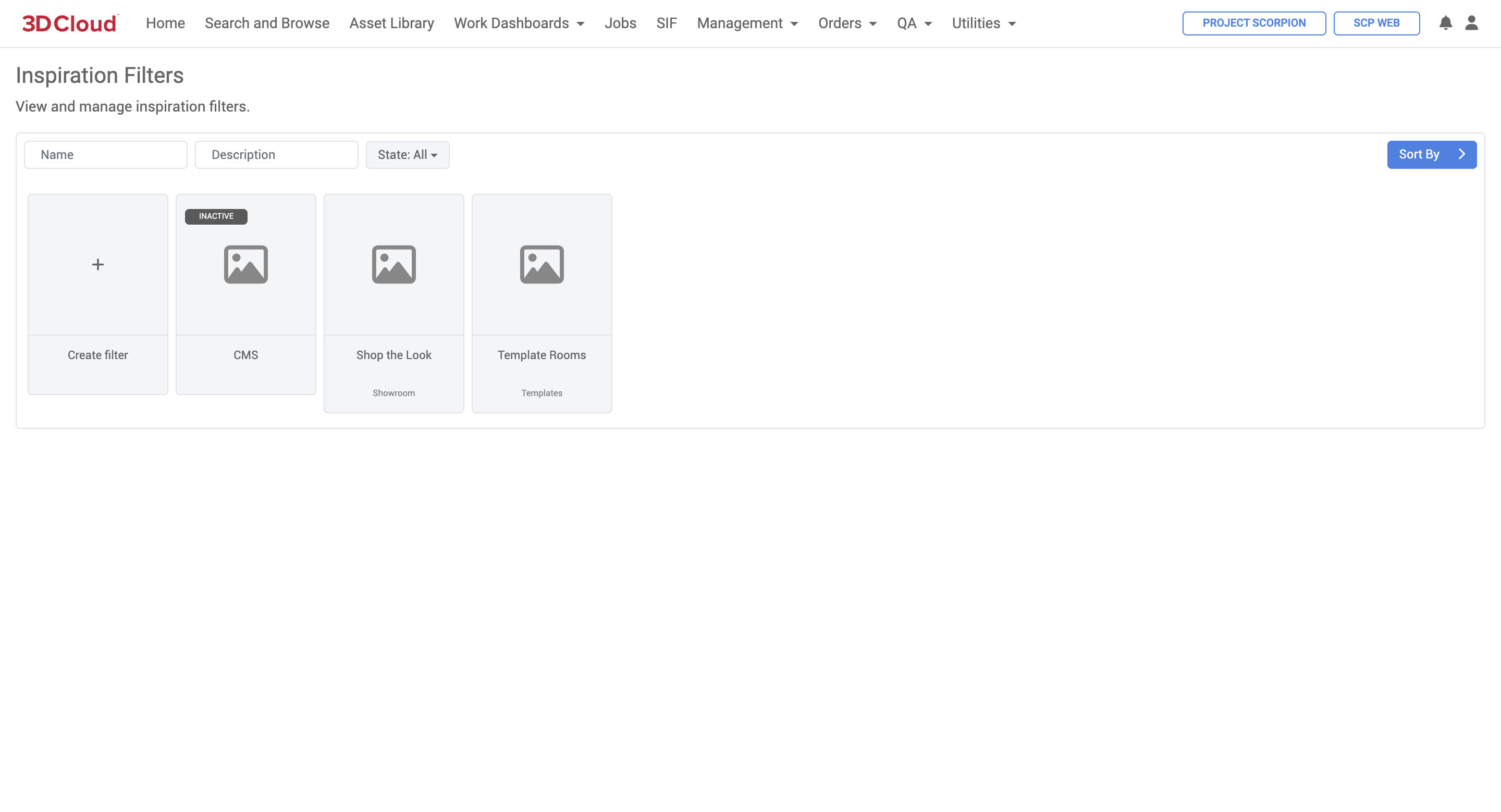
Adding a New Inspiration Filter
Click the Create Filter card on the Inspiration Filters overview to create a new filter.
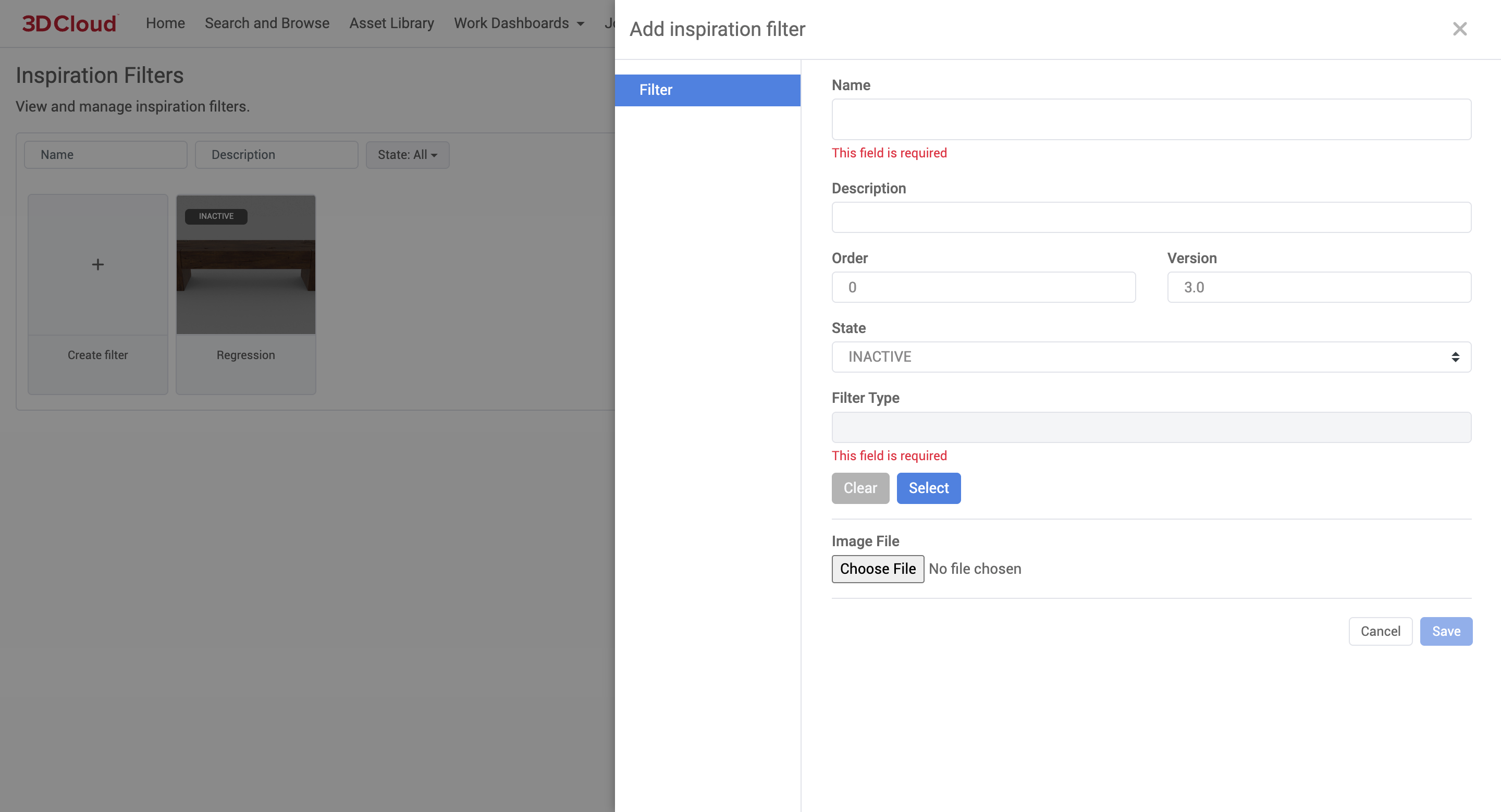
Once the filter has been added, you can manage its options.
To edit an existing filter, click the Edit (tools) icon on the top-right of the filter card.
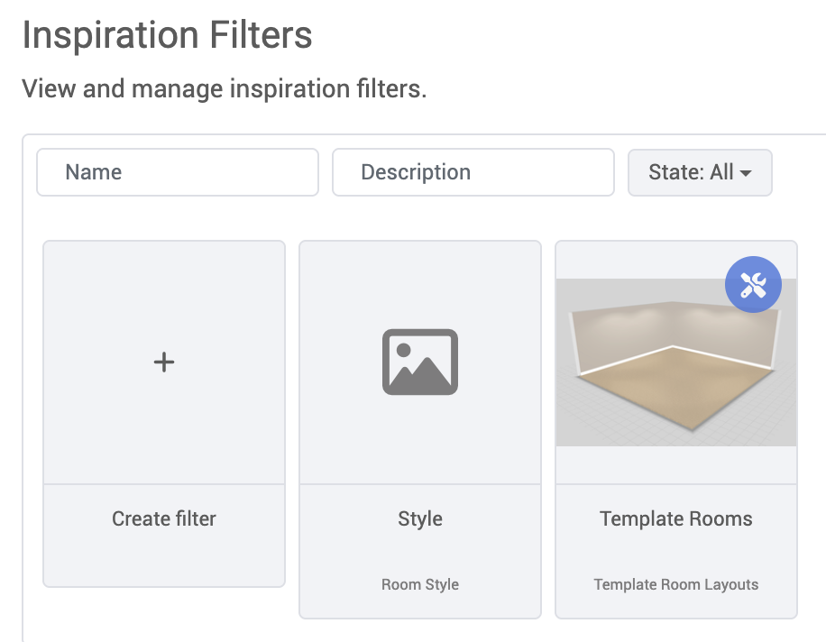
Adding/Editing Filter Options
Filter options must be edited in the context of an inspiration filter. When viewing the edit dialog of an existing inspiration filter, click the Options tab on the left-hand side.
Click Add New to add a new filter option, or click the Edit icon on the right-hand side of an existing filter option.
To add a new inspiration hero to this option, click the Add hero button, where you can search for heroes that exist for the current client.
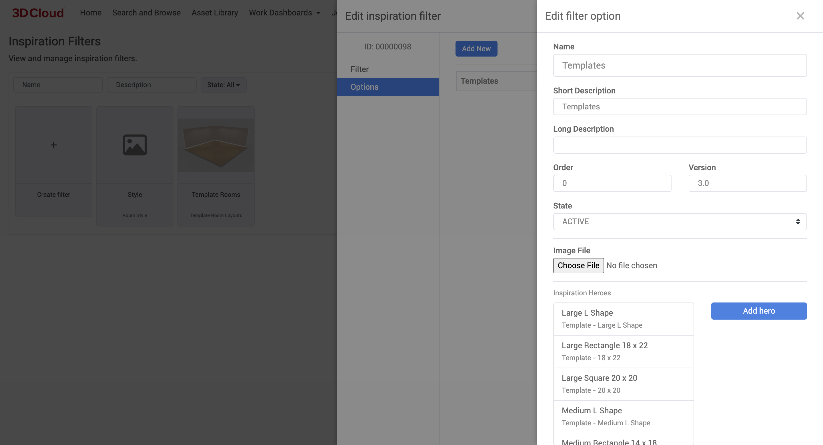
Inspiration Hero
The 3D Cloud AMS Inspiration Hero utility allows you to prepare “inspiration” images for use in our applications, as well as provide metadata for design elements. At 3D Cloud, inspiration images are referring to a 2D image of a room, which a user will click to instantly load a 3D version of that room or drag and drop products from that 2D image into 3D space.
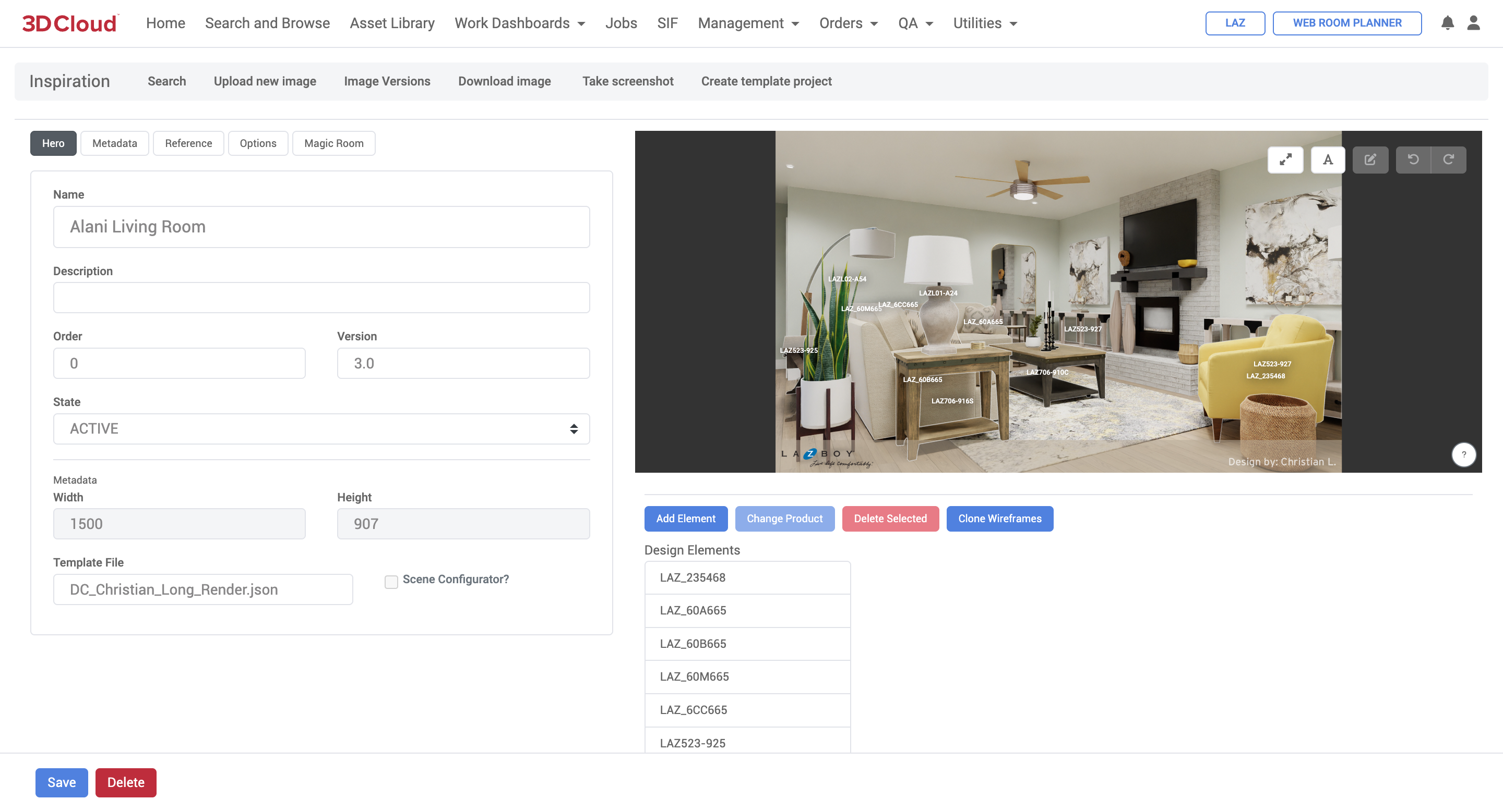
Inspiration Wireframing
Adding a New Design Element (a.k.a Wireframe Product)
Adding a design element will allow for the wireframing of a product, as well as the editing of metadata. To add a new design element to an inspiration hero, click the Add Element button below the wireframe image. Select a product(s) from the product loader. This will add these products to the Design Elements list, and automatically enter drawing mode in the wireframe.
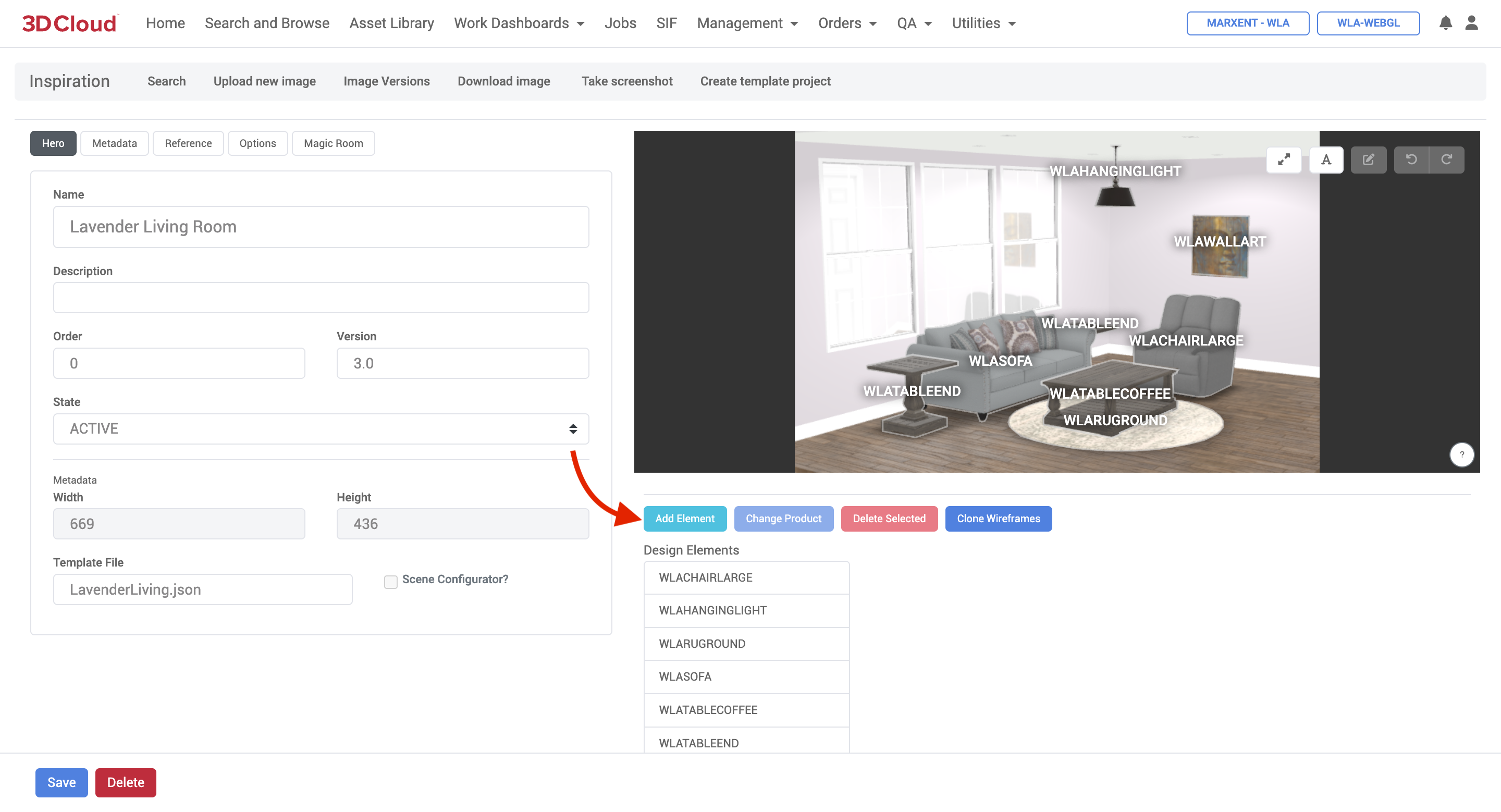
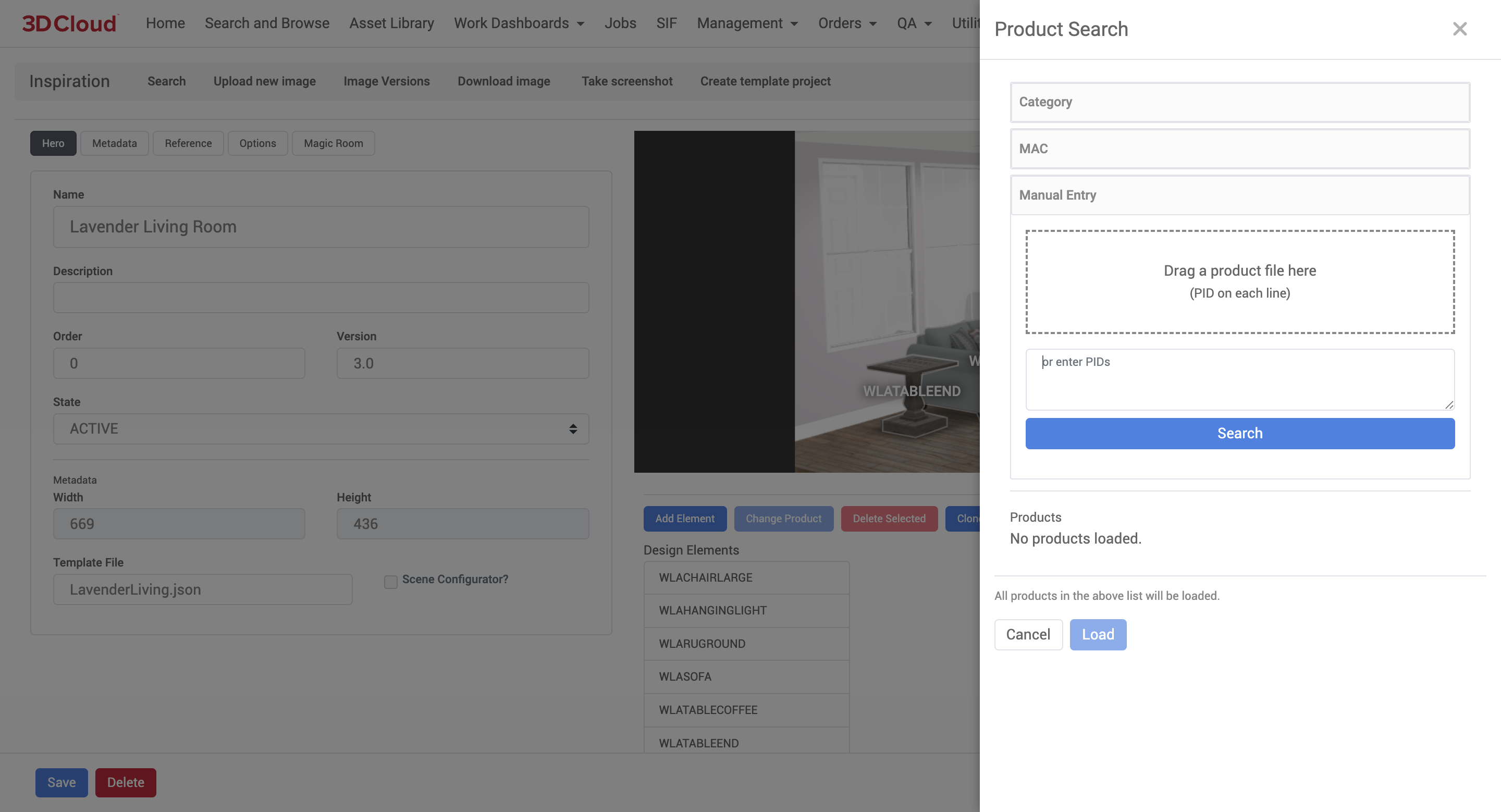
To begin wireframing, hover your mouse over the inspiration and click to place points. A wireframe product must have at least three points to be considered complete. When finished placing points, double click on an existing point, or hit the ESC key.
.png)
To place a preset square rather than drawing a full wireframe, simply hold down the ALT key (Option on Mac) and click once in the inspiration image.
Editing an Existing Wireframe
To select an existing wireframe, click anywhere in the product’s wireframe polygon in the inspiration image, or select the product from the Design Elements list.
Moving an Existing Point
To move an existing point, simply click and drag on the point.
Adding/Removing Points
Hold the ALT key (Option on Mac) while hovering over the inspiration image and click to add a new point. If hovering over an existing point, clicking will remove the point.
Redrawing an Element
To redraw an element’s points completely, press the ENTER key, or the Redraw Selected button on the top-right toolbar in the inspiration image. The same drawing rules/controls apply as when adding a new design element.
Other Controls
Panning/zooming
Pan the inspiration image by clicking an dragging in the inspiration image (not on an existing point), or with the arrow keys.
Zoom into the inspiration image with the mouse wheel.
Undo/Redo
Actions taken in the wireframing tool can be undone/redone with the top-right toolbar, or with CTRL+Z (Command+Z) and CTRL+Y (Command+Shift+Z) key combinations.Toggle product labels
Product labels can be disabled in the wireframing tool by clicking the Toggle Labels button in the top-right toolbar.
Reference Imagery
Click on the Reference tab on the left-hand panel to manage reference imagery for inspiration heroes.
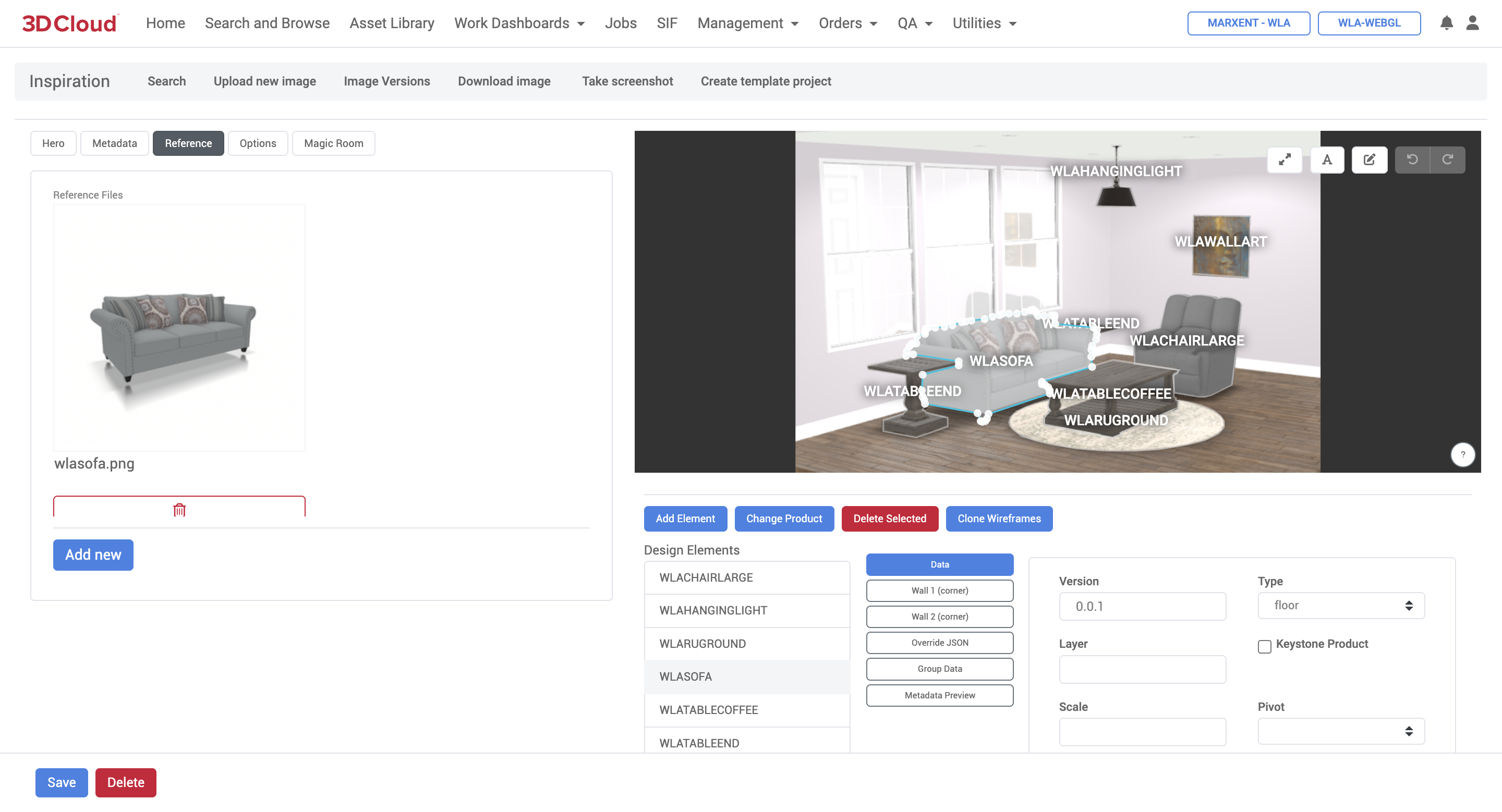
Adding a Reference Image
To add a reference image, either drag an image over the Reference panel, or click the Add New button.
Deleting a Reference Image
To delete a reference image, click the X button below the image.
Attach the Current Inspiration Image Screenshot
Click the Take Screenshot button on the top toolbar to take a screenshot of the current wireframe scene. When prompted, click Yes to automatically upload as reference.
Template Project Creation
Template projects can be created from existing user projects, which can then be attached to the current inspiration hero as a Template File. Click the Create Template Project button on the top toolbar to get started.
.png)
Find the user project you’d like to use as a template in the filter list, and click to select it. The Template Name field will be used as the template filename.
The resulting project will be saved under the template_projects directory on GCP for the selected client application.
IP Whitelist
The 3D Cloud AMS IP Whitelist utility is client-specific tooling to allow administrators to safely add IP addresses to a whitelist. Mutliple IP addresses associated with certain clients can be whitelisted for various purposes, such as accessing specific environments or applications.
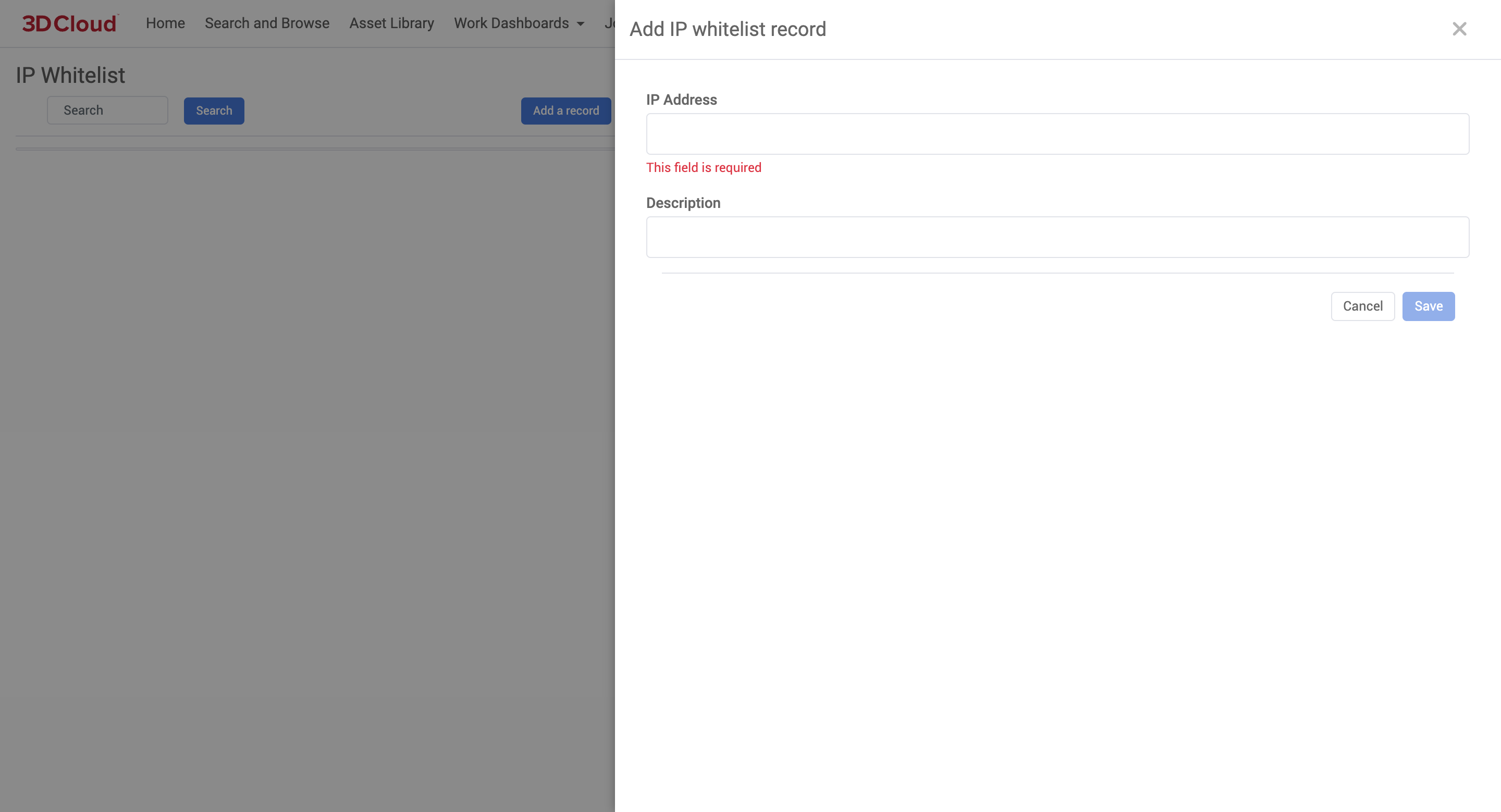
Load Balancer Mapping
The 3D Cloud AMS Load Balancer Mapping utility is a client-specific tool that was developed for use in staged enterprise rollouts to route specific store locations to different sites.
Product Renderer
The 3D Cloud AMS Product Renderer is the utility used to generate photorealistic 2D images from single 3D product(s) or Product Configurators on the platform.
A few sample HD Renders are shown below.
|
|
|
|


.png)
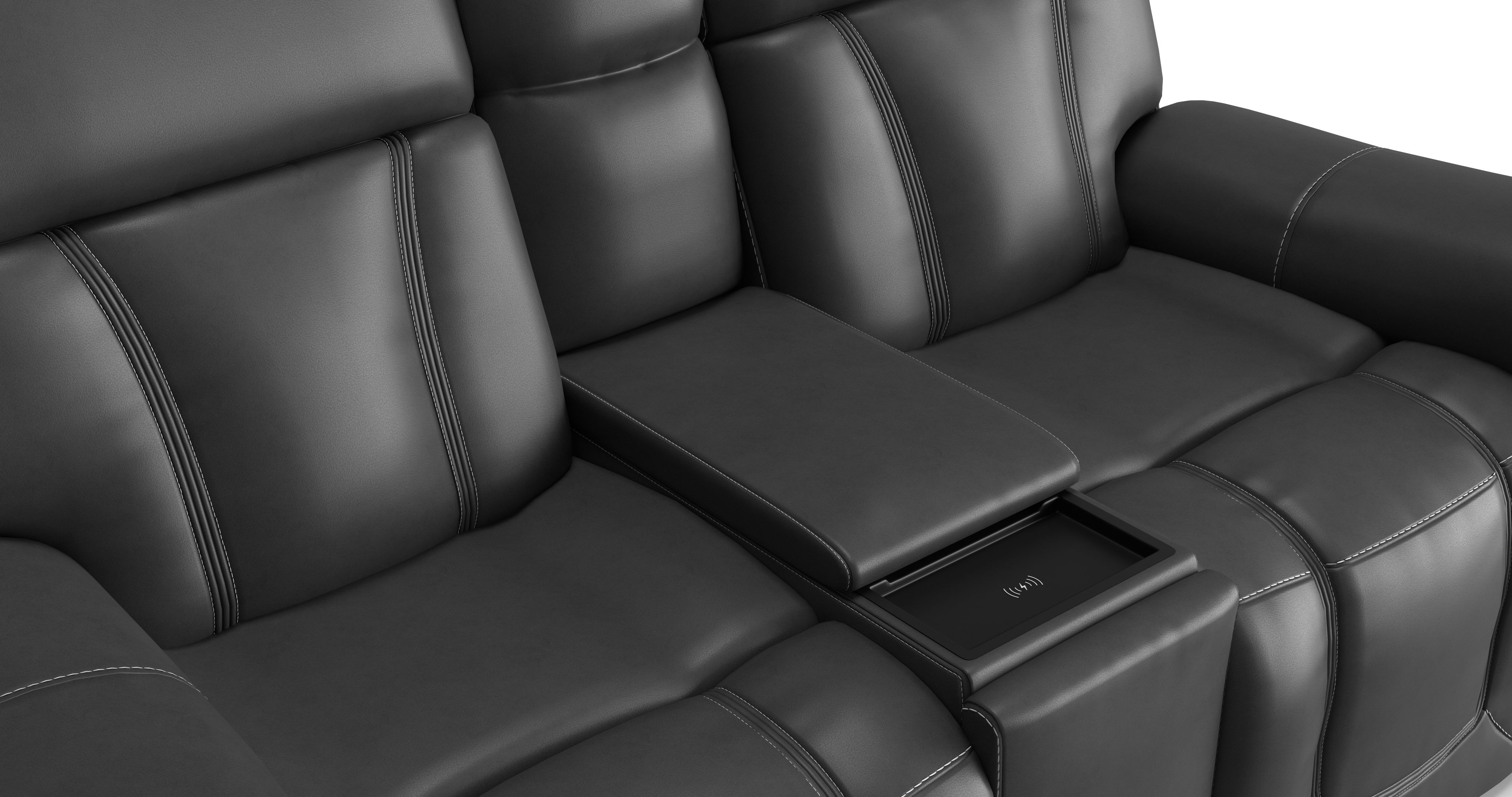
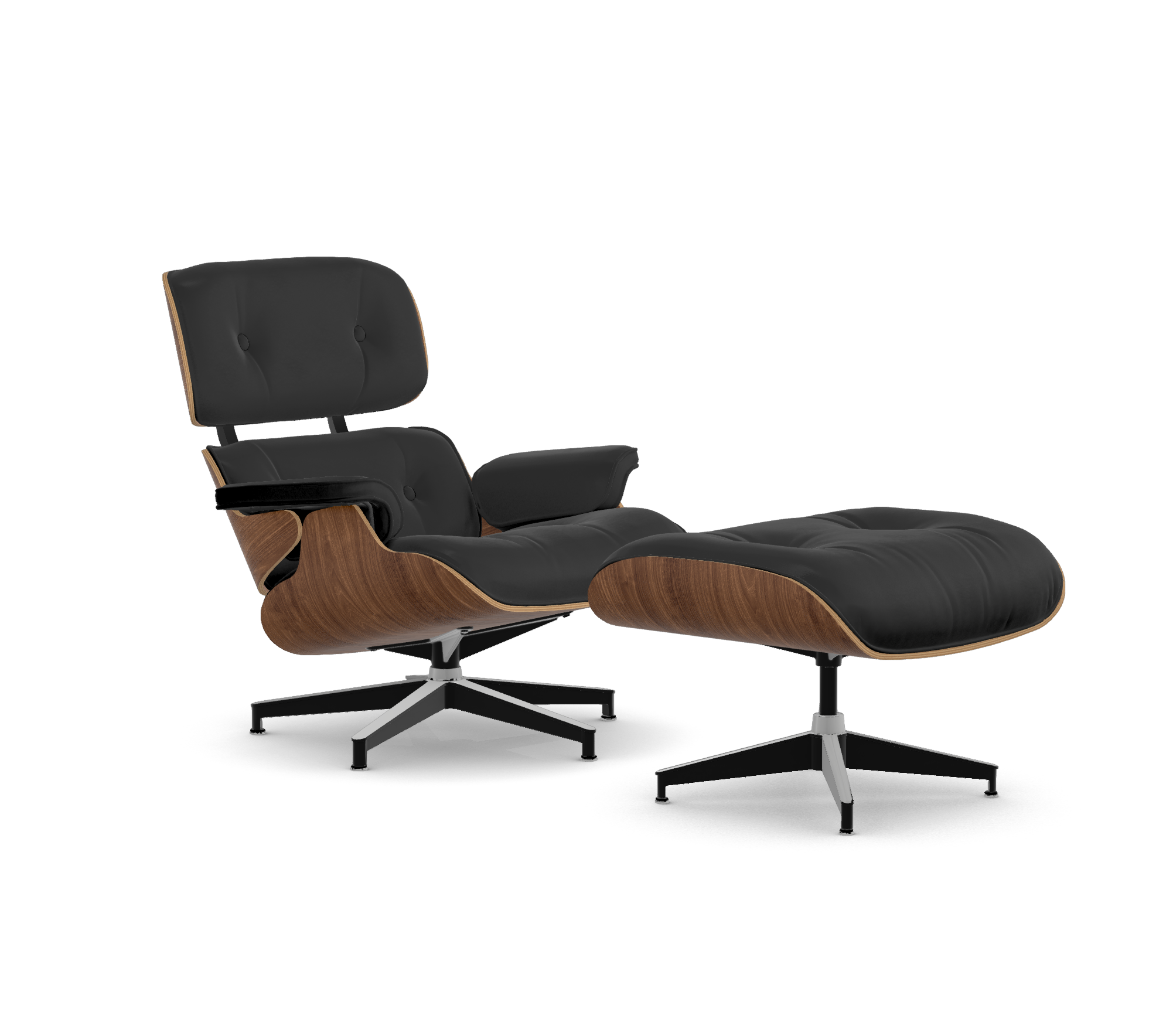
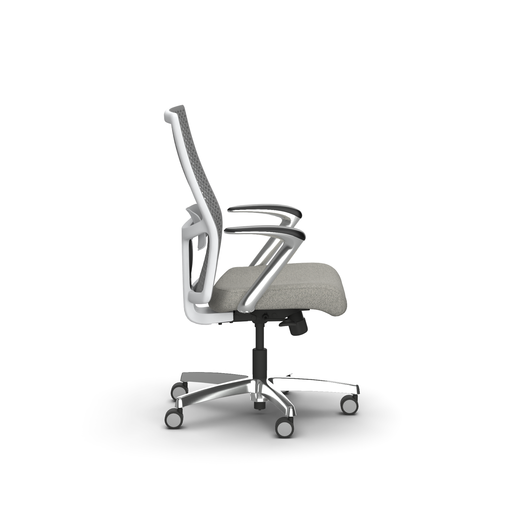
About the Product Rendering Engine
The 3D Cloud AMS Photo Rendering process uses the Cycles rendering engine—a sophisticated, open-source and license-free path tracing renderer which achieves great realism by simulating how light interacts with surfaces and bounces around a 3D scene. The combination of 3D mesh geometry, 3D material properties, camera position and lighting result in product images that can replace photography for Product pages, marketing, catalogs, etc.
The Product Renders feature takes advantage of our real-time 3D player to preview virtual camera positioning, while applying lighting, HDRI and various other rendering controls to achieve photo-realistic final results.
3D Cloud AMS Product Rendering Guide
A separate Product Rendering Guide has been created to provide visual examples of the various Advanced Options settings being applied, and the rendered results. This guide is useful in the planning of Custom Presets, Bulk Render Jobs, Dimension Renders and more. The guide can be viewed as a Google Slides presentation here:
https://docs.google.com/presentation/d/1R053_mW-2FArjVzqDQLc8j6QbYdbMDPW4JTIBCTiHDw/edit?usp=sharin
Accessing HD Renders
The product rendering feature can be accessed in a number of ways:
Via the Utilities → Product Renderer section;
By selecting the HD Renders button while on any single product description page;
Navigating to Utilities → Product Configurator within the AMS;
Initiating a product render from a public-facing product configurator.
Use Cases
There are multiple use cases where Product Rendering can be used. The following table describes the different options a user may choose to create one or many renderings of 3D products.
Product Rendering Type | Accessed via… | Source of Renderings | Angle Options | Description |
|---|---|---|---|---|
Single Product HD Render | AMS Product Detail Page or Utilities → Product Renderer page | ProductID | Unlimited | Single 2D image request produced from a single product (up to 8K) |
Single Product Bulk HD Renders | AMS Product Detail Page HD Render → Bulk Request tab | Bulk Order Sheet (.xlsx) with list of ProductIDs | Unlimited | Multiple 2D images produced in a single bulk order request |
Single Product Spin Render | AMS Product Renderer | ProductID | 32 preset spin angles + top view | 33 total images (“spin set”) produced in a single request |
Product Configurator HD Render | AMS Product Renderer | Single SKU in Configurator | Unlimited | Single 2D image request of a specific configuration at a specific angle |
Product Configurator Bulk HD Renders | AMS Product Renderer | Comma-separated list of SKUs in bulk input form | Unlimited | Multiple 2D images produced of multiple configurations at a specific angle, in a single bulk order request |
Product Configurator Spin Render | AMS Product Renderer | SKUs in Configurator | 32 preset spin angles + top view | 33 total images (“spin set”) of a specific configuration produced in a single request |
Product Configurator Rendering On Demand | Public-facing configurator | Specific configuration | Preset: Front 45°, Front, Back, Left, Right, Back 45° | Download HD Renders feature
|
Modular Configurator | Not yet supported | Not yet supported | Not yet supported | Not yet supported |
Room Planner | Public-facing | Room scene | Unlimited (camera positioning in Room Planner) |
Key Rendering Terminology
Render
The 2D image output that is produced by a 3D computer-generated image process, from a 3D model, applied virtual materials, camera positioning and lighting settings.
Resolution
The rendered image pixel size, in width x height. Resolution can be set anywhere from small thumbnails (e.g. 720 px x 720px) up to 8000 px x 8000px or more. When you hear the terms “2K, 4K, 8K” this typically means resolutions of 2000 px × 2000 px, 4000 px × 4000 px, 8000 px × 8000 px respectively (or close to these).
HDRI
An HDRI ((High Dynamic Range Image, also known as a “Skybox”) is a virtual, projected lighting environment that is used to control lighting and color tones on an image. Think of it as a virtual “studio setting” that is used in the rendering process to achieve photorealism similar to shooting a photo in a specific photo studio environment.
HDRI images are typically in a spherical panoramic format, which 3D Cloud converts to cube maps (six square faces) for optimal GPU performance and accurate image-based lighting in our 3D rendering workflow. The cube map wraps around 3D models like an invisible sphere, projecting realistic lighting from all directions.
.png)
Example HDRI used for 360° Spin Renders
Presets
In the 3D Cloud AMS, a Preset is specific set of stored camera position, camera settings, lighting settings, and other Advanced Options parameters that are saved for use on one or more render jobs. These “Presets” are used to create templated cropping and lighting scenarios that can be used across products and product categories, in single or bulk render jobs.
The main reason to use a Preset is to save time setting up your desired render configuration before submitting a render job.
When a Product is loaded into the Product Renders 3D preview window, clicking on a saved Custom Preset “snaps” the camera into position and applies all of the preset resolution, camera and lighting settings.

Custom Presets
Every Preset has a unique Preset ID which can be viewed when you click on the “expand arrows” icon when you hover on the upper right of the Preset thumbnail image.
| 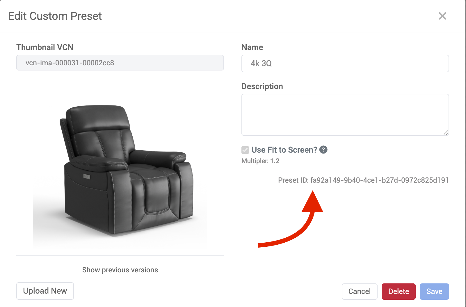 Viewing a Preset ID |
|---|
If you ever need to copy the current Preset ID (for use in a Bulk Render Request sheet, for example) you can click on the “Copy” icon in the lower right of the 3D product preview window and then select “Copy Selected Preset ID”.
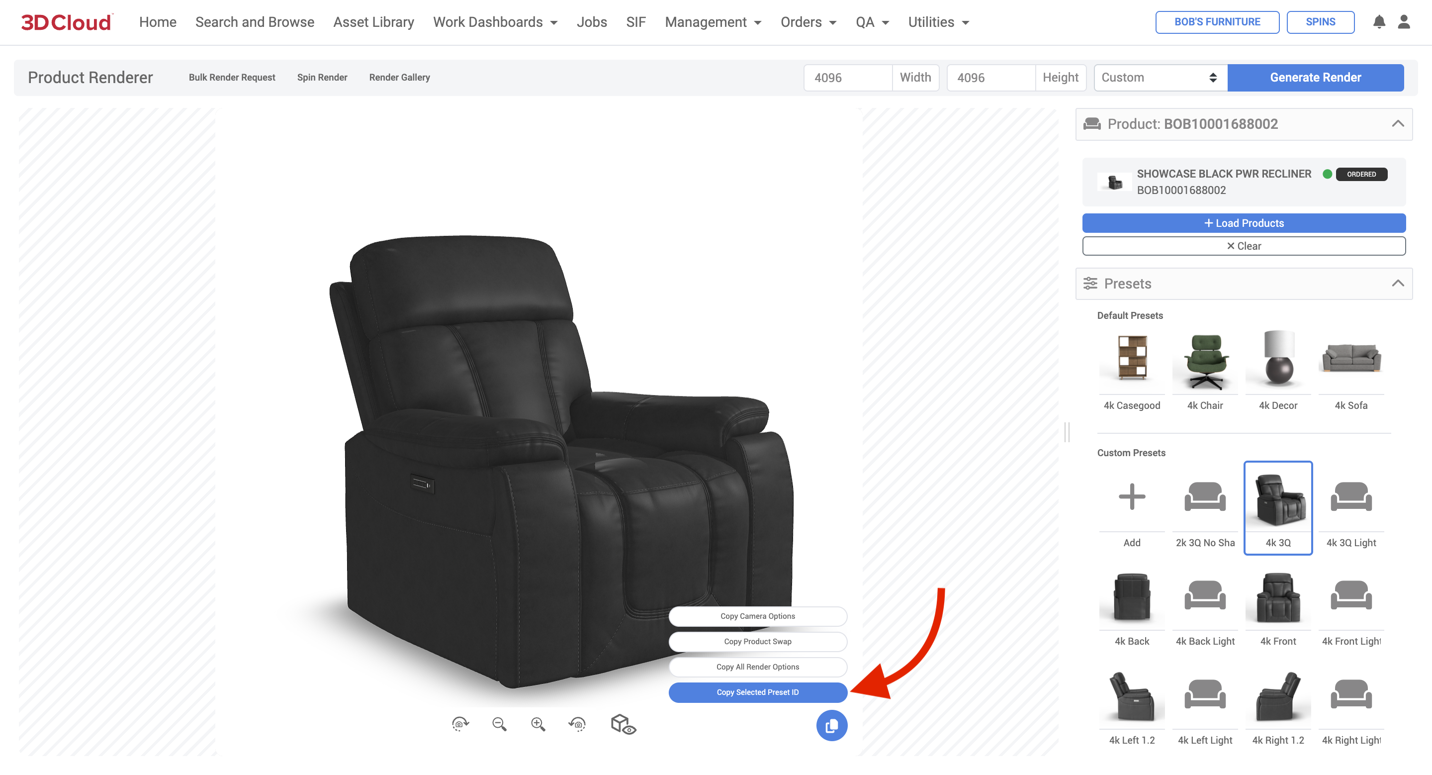
Copy Selected Preset ID button
How to Create a Custom Preset
Go to the Product Renders section and load a product.
On the Product Render view, you can select an existing preset (as a starting point for a new preset).
Currently, presets can only be created, but not edited.Set your desired camera and lighting settings under “Advanced Options”.
Note: The 3D preview window will dynamically show the Camera Position and Scene settings, but will not provide a real-time preview of the Lighting settings or the exact angle of the rendered shadow.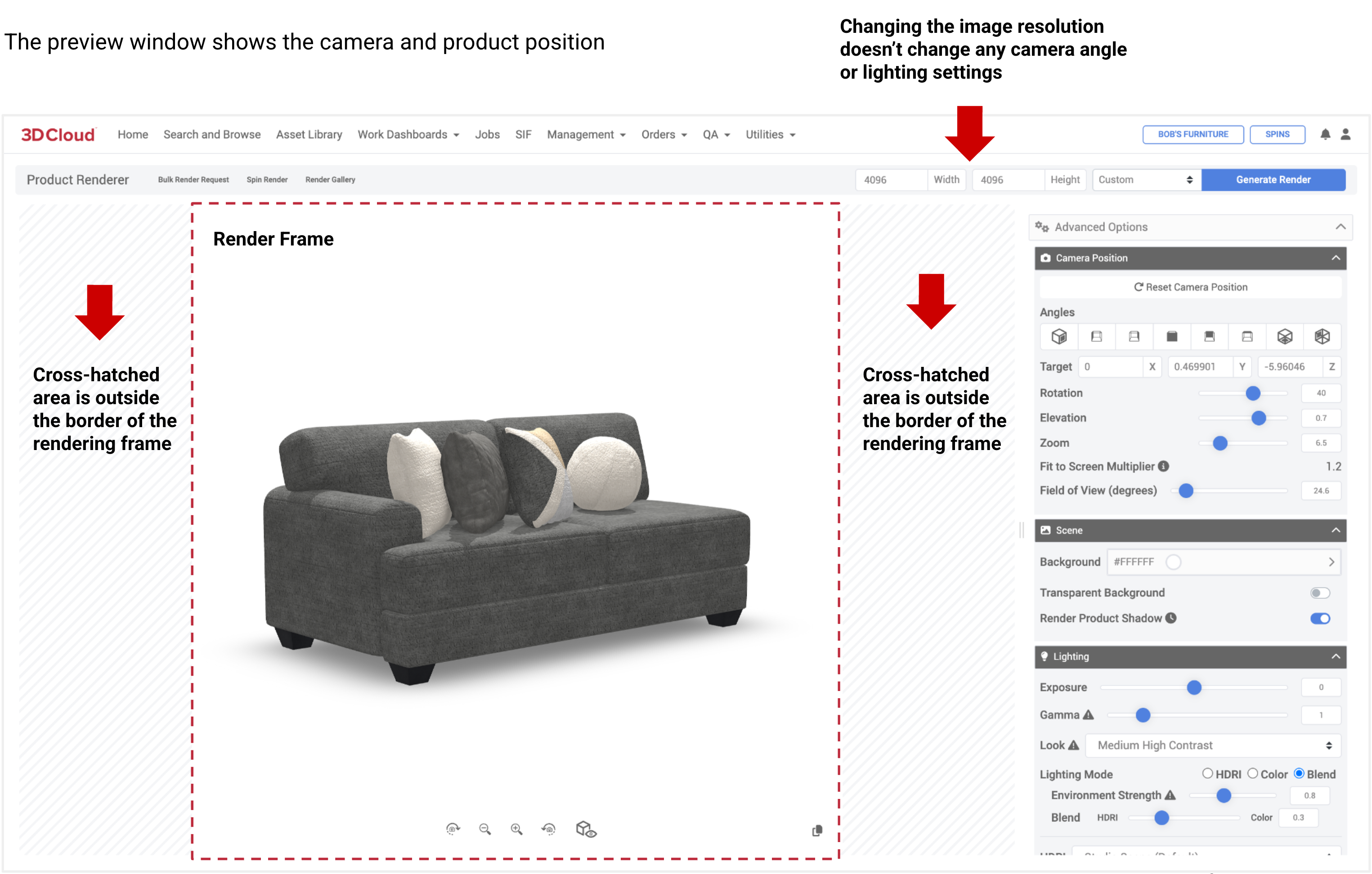
When setting presets, take note of the Fit-to-Screen Multiplier value. If it is less than 1.0 the product may render too large for the image canvas. The “sweet spot” Fit-to-Screen Multiplier value is around 1.2.
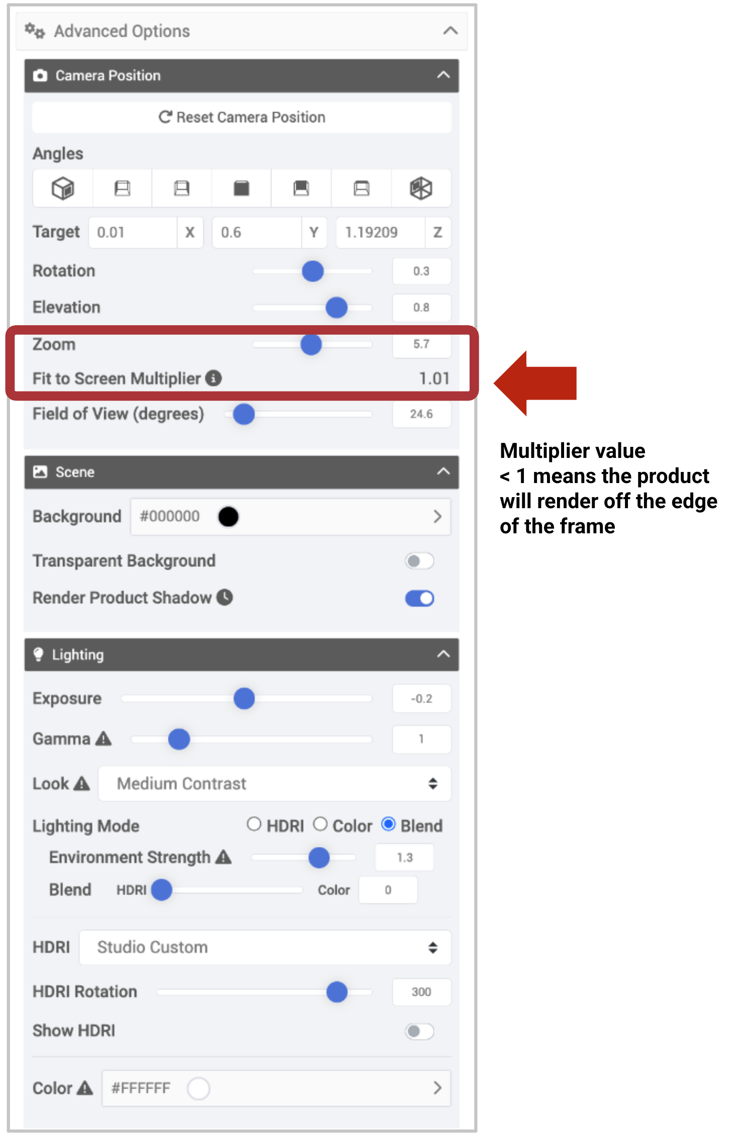
When you are done with settings, click the “Create New Preset” button at the bottom of the right hand panel.
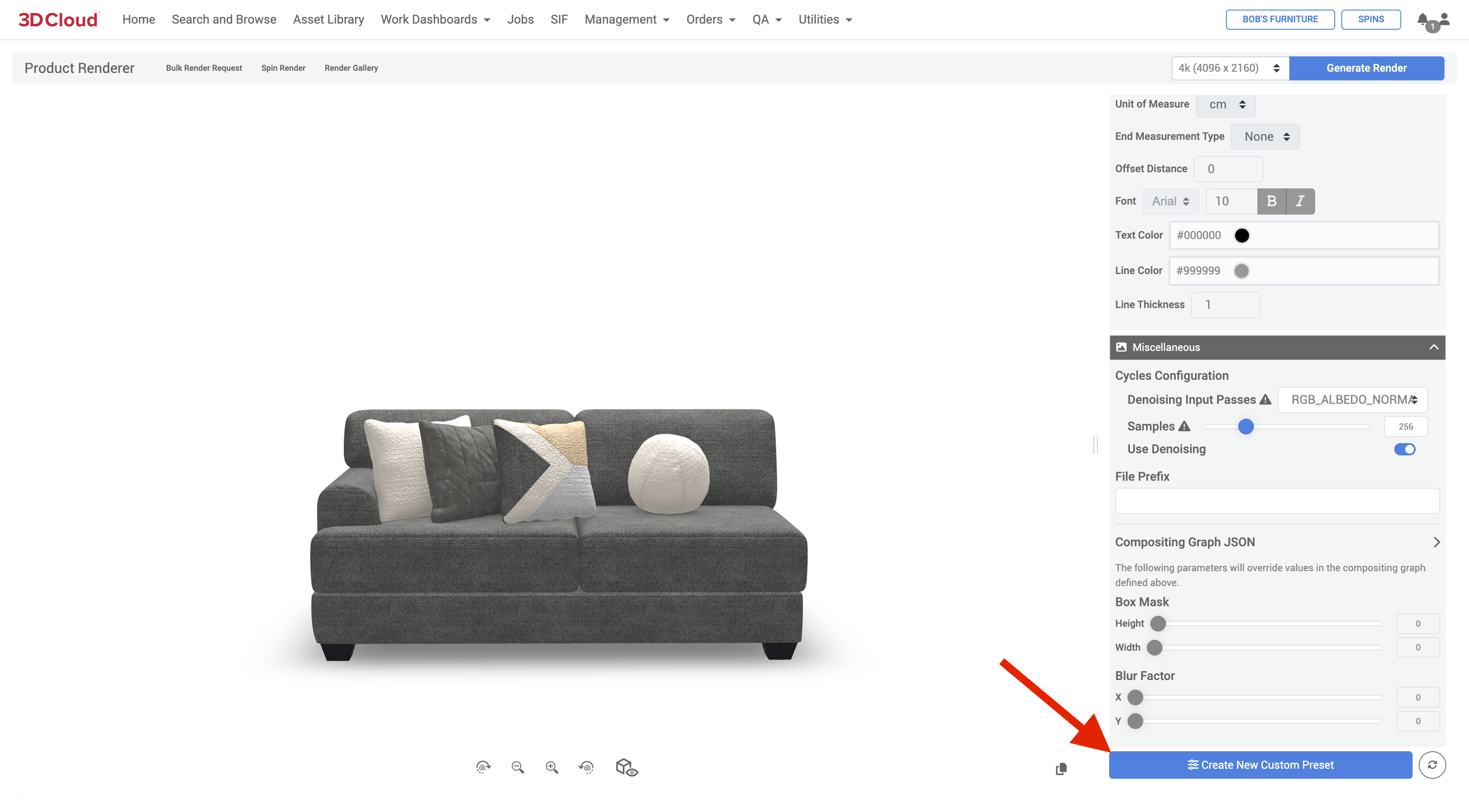
After creating the new custom preset, the copy icon in the lower-right of the 3D preview window can be used to Copy the Selected Preset ID, Camera Options, Product Swap, or All Render Options for use in a bulk render sheet.
.png)
You will be prompted for a Preset Name (required), Description (optional) and whether or not you want to use the Fit to Screen multiplier value.
If you check the “Use Fit to Screen” check box, any product rendered with this preset, regardless of size, will be scaled on the canvas to approximate the same amount of white space around the product.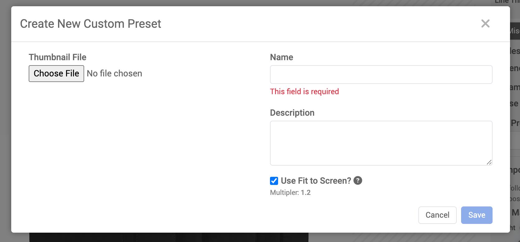
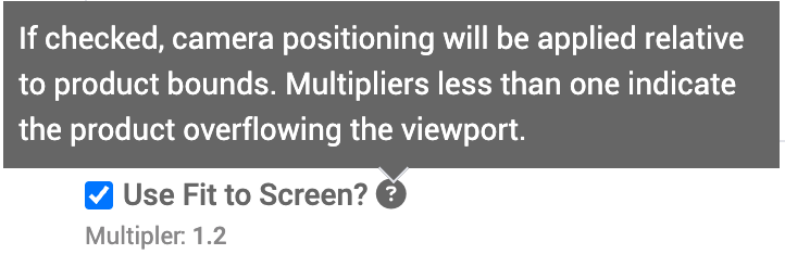
You can also choose to upload a square thumbnail image to be used as the Preset icon.
Click the “Save” button or “Cancel” to exit without saving.The Preset is now available for use in the Custom Presets area.
Note: In order to create Presets, your user permissions must have the PRODUCT_RENDER_PRESET_MANAGER feature set.
A Custom Preset can also be generated from an existing render in the Render Gallery of a particular product. Just select an image from the Render Gallery so the Render Info panel is displayed, and click the “Create Preset” link in the Render Info area.
.png)
Creating a Preset from an Image in the Render Gallery
Single Product Renders
Single Product Renders is the term given to the process of generating a rendered image of a single particular product at a particular camera angle. Each render “job” is submitted one-at-a-time, rather than in a batch job—typically requiring individual camera positioning and lighting adjustments.
Initiating a Product Render
A product render can be initiated on the Utilities → Product Renderer page, or from any individual Product Description Page.
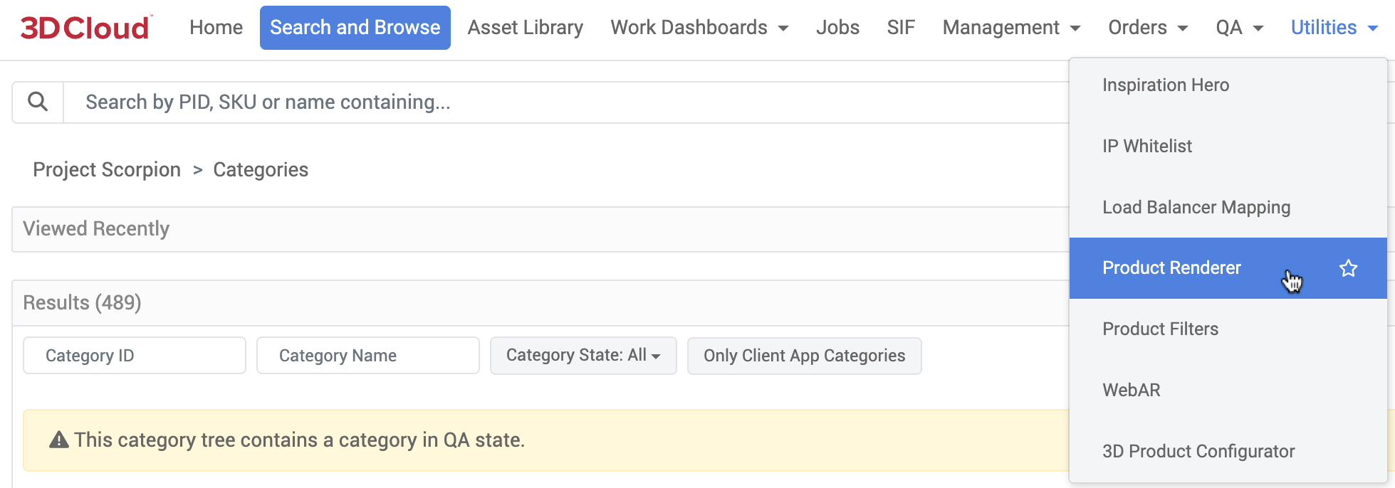
Product Render Search
When loading the Product Renderer tool, the Product Render Search panel will slide out from the right automatically with the ability to search by category, PID, SKU or name. You can then multi-select the products desired to render, and click the “Load” button at the bottom of the page.
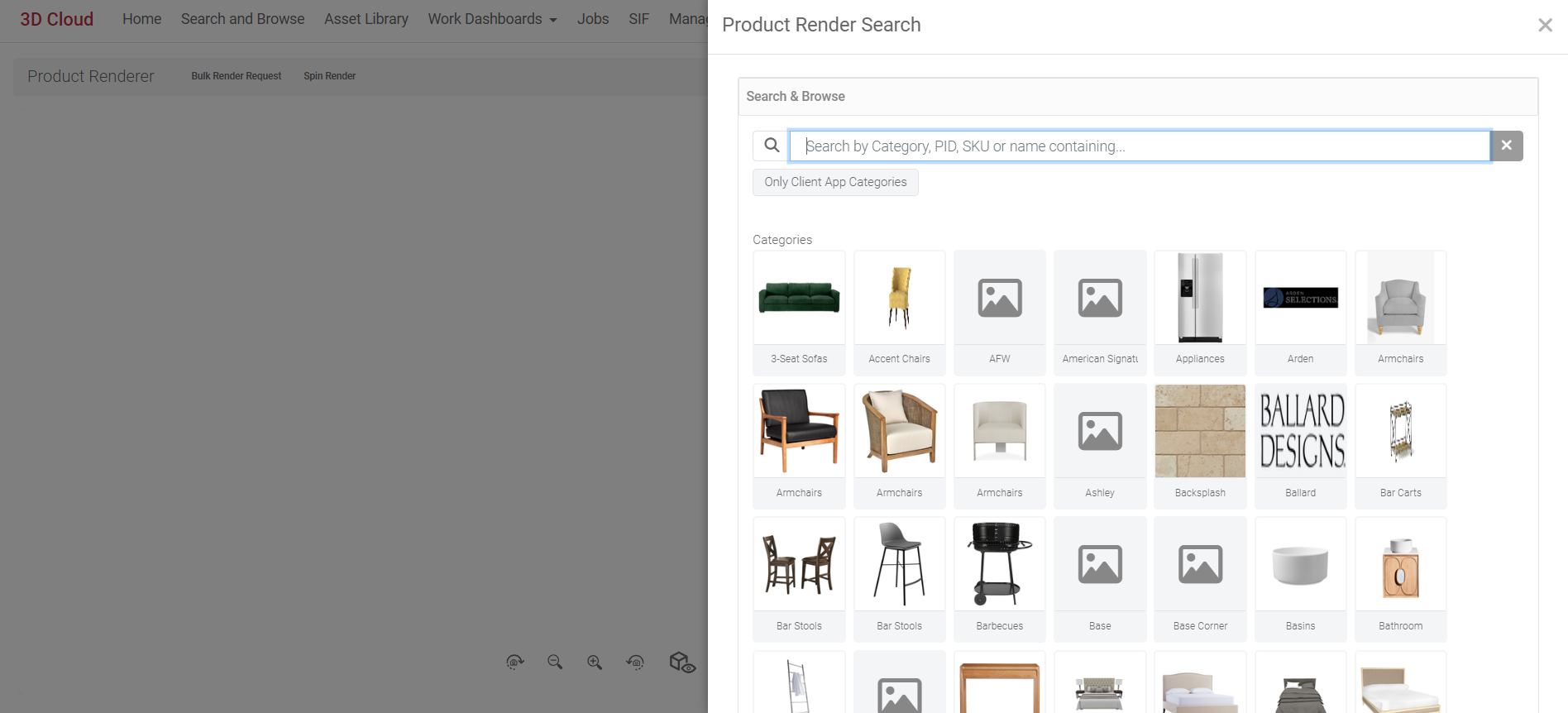
After loading your desired product(s), the Product Renderer Search page will automatically close and the user will be brought to the main Product Renderer WebGL viewer with the first producdt loaded. An options panel on the right-hand side is displayed with Customize, Presets and Advanced Options accordion-style drawers.
Rendering Resolution
The desired image resolution (in pixel width x height) can be entered at the top of the page next to the “Generate Render” button. The dropdown menu allows selection of standard resolutions:
Proof (1280×720)
2k (2048×1024)
4k (4096×2160)
8k (7680×4320)
Custom width and height entry (Note: The smallest allowable resolution is 256×256)
.png)
Customize
The Customize menu is displayed when the Product ID loaded is part of a configurable assembly. The swappable assembly options are displayed in accordion-type menus. The Customize menu will not be visible if your Product does not have an Assembly for Swapping.
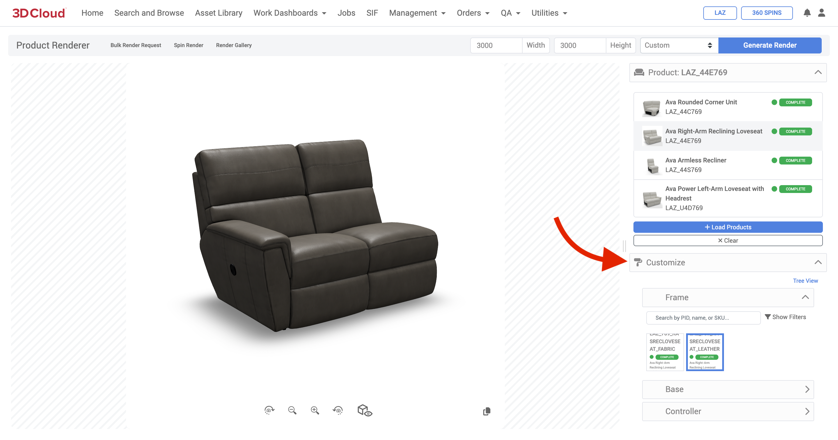
Product with Assembly Swappable Options: Customize Panel – List View (Default)
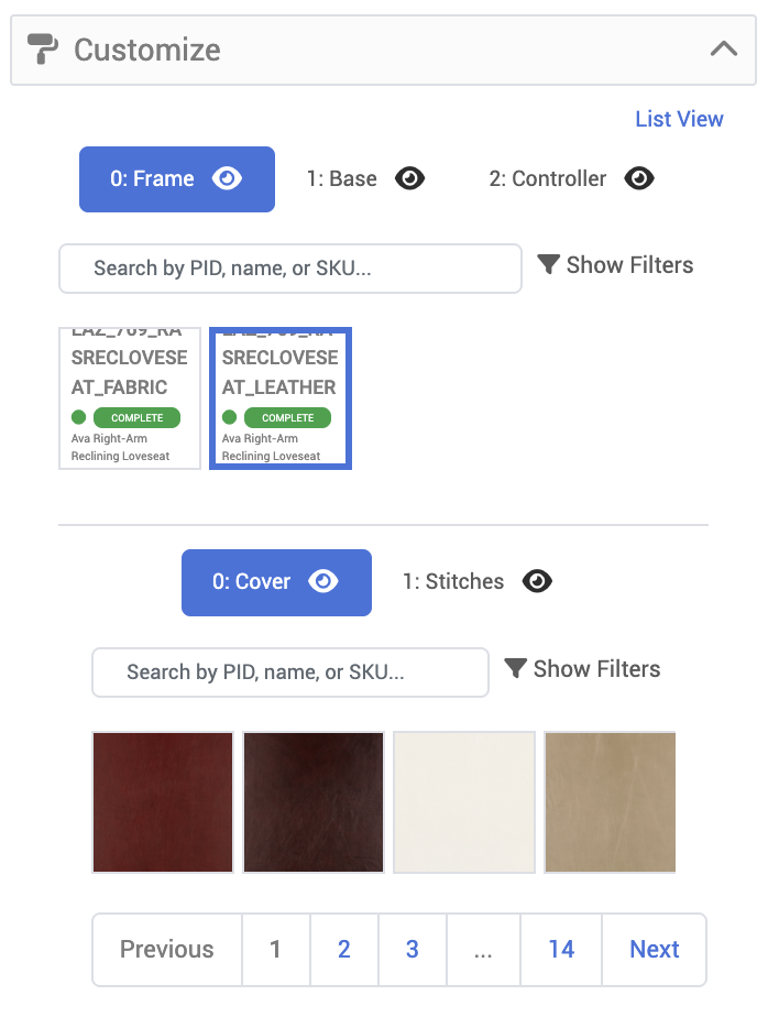
Customize Panel (Tree View)
Advanced Options Panel
The Advanced options panel provides multiple ways to adjust the Camera, Scene and Lighting controls that will affect the final render.
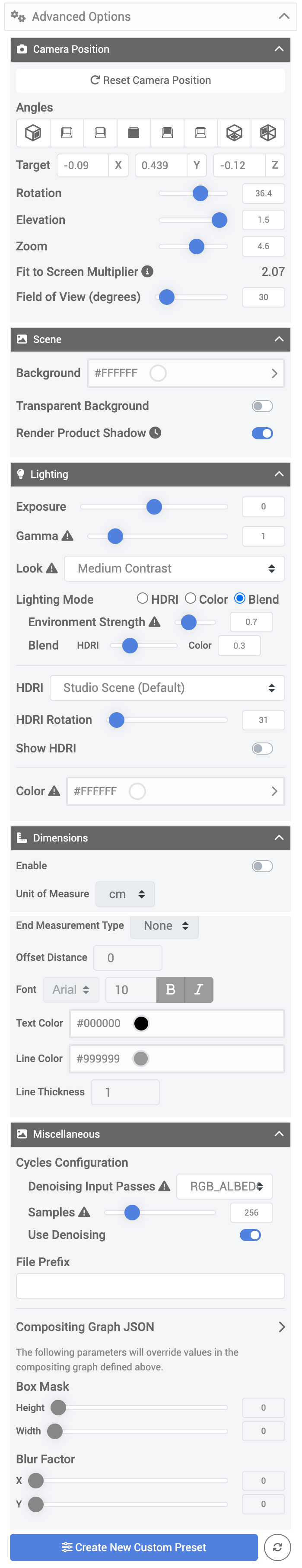
A summary of Advanced Options settings are provided below.
Visual examples of the effects of these settings are provided in our Product Rendering Guide.
Advanced Option Category | Setting | Description |
|---|---|---|
Camera Position | Reset Camera Position | Resets the camera position to Front view (0° camera rotation) |
For rendering, the platform supports the rotation, elevation, zoom level and field of view of the camera around the product. | Angles | Jump links to preset angles (Front 45°, Left, Right, Front, Back, Top, Back 45°) |
Target (X, Y, Z) | X Y Z Float values with input field or arrow selectors to increment values. | |
Rotation | Rotates the camera around the product. 0 to +180° is clockwise from front 0 to –180° is counter-clockwise from front | |
Elevation | The elevation (height position) of the camera relative to the pivot point (generally the floor) 0 = Camera on floor –2 = Camera angle approx. 30° below floor 2 = Camera angle approx. 45° above floor | |
Zoom | Camera zoom level (0.1 to 10.9), default is 3.0 Affects Fit-to Screen Multiplier, can affect the perceived shape of the product due to perspective change. | |
Fit to Screen Multiplier | An indicator of how much of the product is visible in the viewport (canvas). Values less than 1.0 indicate that the product is overflowing the viewport. A recommended value for keeping ample white space around the product is 1.2. | |
Field of View (degrees) | Controls the field of visible camera capture. 0° to 180°, default is approx. 30° Does not skew the shape of the product. | |
Scene | Background | The background color behind the product (Hex value); can be set with color picker and includes opacity level as well (0 to 1, where 1=Opaque) |
Controls for the background and product shadow | Transparent Background | Toggle button to render with or without a background. Note: Turning on Transparent Background will disable the HDRI Skybox |
Render Product Shadow | Toggle button to render with or without a product cast shadow Rendering with shadows will increase your render time. | |
Lighting | Exposure | Used to control the general brightness of an image. -10 to +10 default is 1.0 (typical ranges are –2 to +2; usually tweaked in 0.1 increments to dial in exposure) |
Lighting controls for exposure, contrast and environment. | Gamma | Used to control how smoothly black transitions to white in an image Not previewable: Changing this option will only be reflected in the final render. |
Look | Dropdown menu with None, Very Low Contrast, Low Contrast, Medium Low Contrast, Medium Contrast, Medium High Contrast, High Contrast, Very High Contrast. | |
Lighting Mode | HDRI = Uses the HDRI texture as the environment map in Blender Cycles when rendering environment lighting Color = Uses an RGB color specified by the user (default is #FFFFFF white) when rendering environment lighting Blend = Uses a mix node that blends both the HDRI and the Color option together using the value of the Blend property as a percentage (0 to 1) Example 1: Setting the lighting mode to Blend and using Environment strength of 0.7 (70%) and Blend value of 0.3 (30%) would:
| |
Environment Strength | The relative effect of the HDRI or Color environment on the product lighting. | |
Blend | The relative percentage (0 to 1) effective between the HDRI environment vs. the Color environment on the product lighting. 1 = 100% Color environment | |
HDRI | HDRIs (High Dynamic Range Image) that can be selected for use as an environment lighting scene. Currently seven (7) HDRIs are available to use. Custom HDRIs are possible to be set up per client. | |
HDRI Rotation | The rotation value of the HDRI scene (0° to 359°) | |
Show HDRI | Toggle to hide or show the HDRI in the Preview window and render | |
Dimensions | Enable | Toggle to enable or disable a dimension lines and value layer (width, depth and height) on product renders |
Controls for dimension line and values overlay. | Unit of Measure | The displayed units of measure for the width, depth and height values on the dimension lines overlay. Options are: m = meters (3 decimal points) cm = centimeters (1 decimal point) mm = millimeters (no decimal points) ft/in = feet and inches (expressed as fractions to 1/16ths) in = inches (expressed as fractions to 1/16ths) |
End Measurement Type | Options are None or Arrow at the end of the dimension lines | |
Offset Distance | Sets the general offset distance of the lines from the bounding box of the product (0 to 0.2 is the typical range, can be in 0.001 increments) | |
Font | Select from 7 system fonts (Arial, Courier New, Georgia, Tahoma, Times New Roman, Trebuchet MS, Verdana) Font size, Bold or Italic | |
Text Color | Hex value color for the dimension text | |
Line Color | Hex value color for the dimension lines | |
Line Thickness | Thickness of the dimension lines, can be decimal values less than 1. Note: Arrow heads are proportional to the dimension line thickness, so the thinner the line, the smaller the arrows. | |
Miscellaneous | Cycles Configuration: Denoising Input Passes | Dropdown menu with options for reducing noise and other artifacts on textures. RGB, RGB_ALBEDO, RBG_ALBEDO_NORMAL |
Advanced controls for render engine denoising, samples, and shadow falloff. | Cycles Configuration: Samples | The number of samples used in rendering an image using Blender's Cycles rendering engine. 256 is the default sampling rate. |
Cycles Configuration: Use Denoising | Toggle to Use or Not Use Denoising | |
File Prefix | A text prefix string that you would like to have appended on to the front of the render filename | |
Compositing Graph JSON | Compositing Graph JSON is a structure used to describe a collection of Blender compositing nodes, including their socket connections and default values. This JSON is not typically created manually; instead, it is generated using the MXT Blender plugin, which allows users to create a compositing graph in Blender and export it to JSON format. This JSON can then be used to define the compositing graph in rendering configurations. If you need specific Compositing Graph JSON strings, it is recommended to reach out to 3D Cloud Technical Artist Leads for assistance. | |
Box Mask (Height, Width) | Controls the size of the product shadow’s “bounding box”. Slide with values 0 to 1 for Height and Width dimensions Note: Requires Compositing Graph JSON code to enable this feature. | |
Blur Factor (X, Y) | Controls the fuzziness/falloff of the cast product shadow. Note: Requires Compositing Graph JSON code to enable this feature. |
Generate Render Button
The Generate Render button will initiate the render job after all options and settings have been selected.
.png)
Once the render job is submitted, you will see a “toast” alert pop-up from the bottom of the screen notifying that the render is processing.
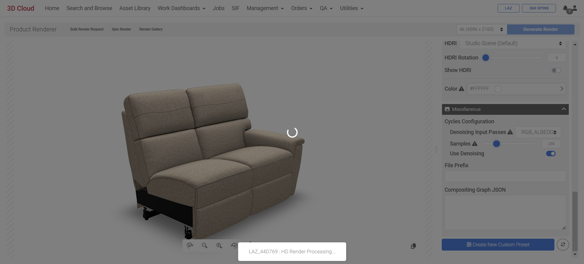
Toast alert: “HD Render Processing…”
Additionally, the notification bell area at the top right of the page will show the “Render processing…” message.
When the render is complete, the notification bell area will show a “Click to download” link.
|
|
|
|---|
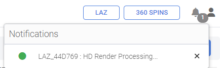
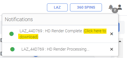
Email Notification
When you click the Generate Render button, or any bulk render job, you will receive an email notfication with the subject line “3D Cloud - Render Complete” (from the email “noreply@3dcloud.io”) when it is completed. The email will have a link to download the image(s), and the image is stored in the Render Gallery for that particular Product.
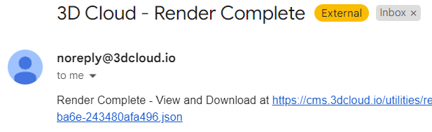
Render Gallery
All renders generated from the back-end will end up in the Render Gallery of the product. The Render Gallery is accessed via the link in the Product Renderer title bar (on any Product Detail → HD Render, or Utilities → Product Renderer page)
![]()
The Render Gallery shows all previously completed renders for a specific Product.
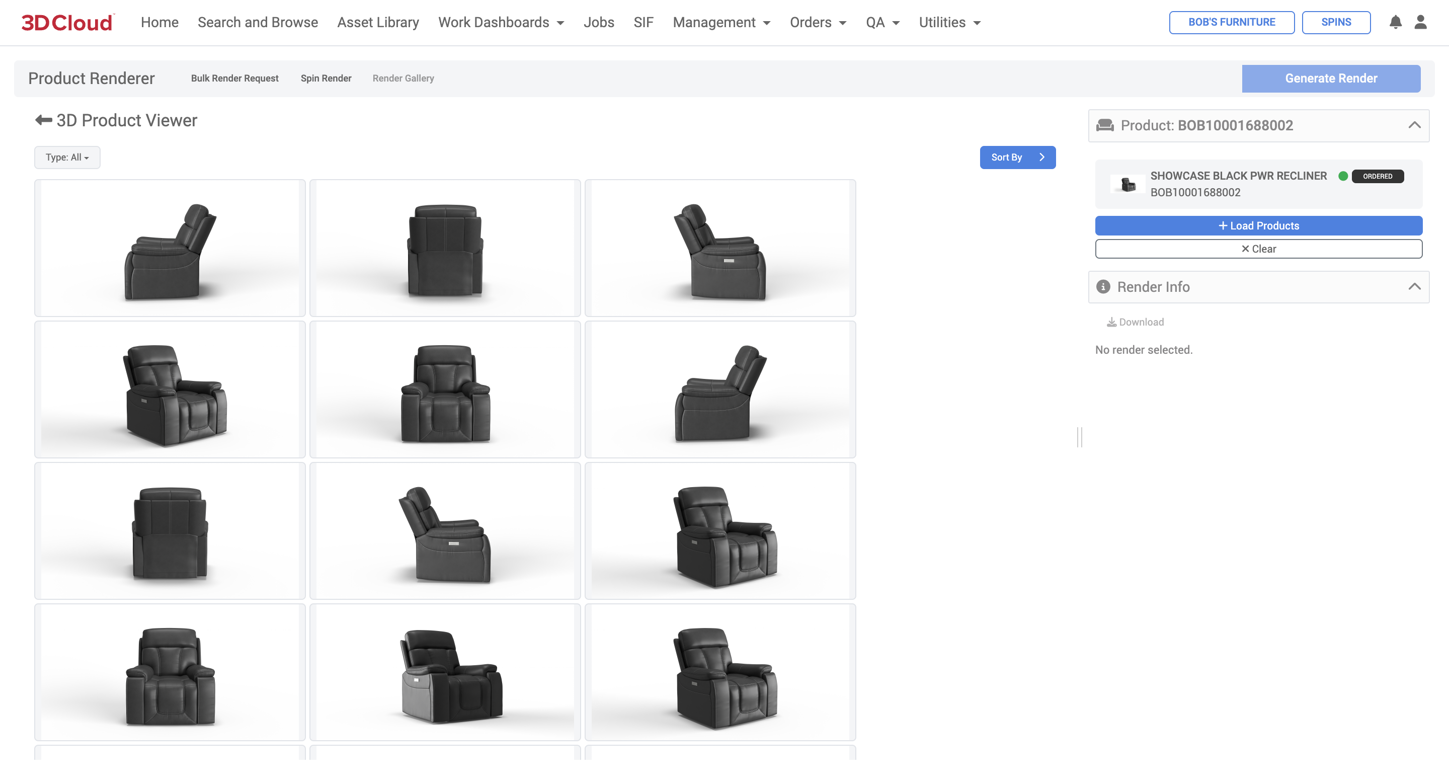
Clicking on any individual render will display the Render Info for that image. Information includes the resolution, creation date/time, and render metadata for that particular image.
Next to the Render Metadata heading, clicking the “clipboard” icon will copy the metadata.
A Download link brings up the full-sized image in a new browser tab, from which it can be saved to your computer (via right-click “Save as” on most browsers).
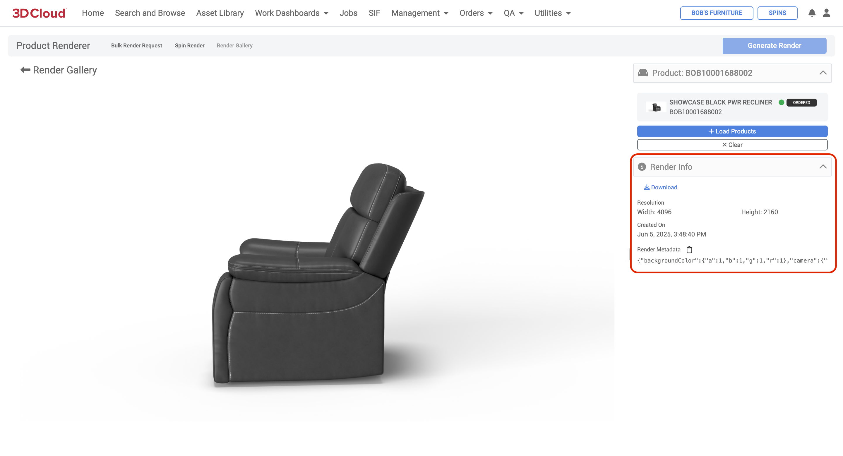
Bulk Product Renders
Bulk Product Renders are possible in the 3D Cloud AMS Product Renderer. This feature allows the user to submit render jobs containing hundreds of renders at one time. Utilizing a spreadsheet xlsx list of Product IDs (one per row), one can create a Bulk Render Request sheet that defines different rotation angles, presets and custom settings.
Planning Your Bulk Renders
When anticipating bulk renders, it is good to have a plan to produce a large volume of renders, across different product categories, color ranges and product placements (Floor or Wall/Ceiling). Key activities in this process include these recommended steps:
Create Presets
Using our Product Rendering Guide (“Which HDRI do I use?” page 27), decide on an HDRI that matches your lighting style (or arrange with the 3D Cloud team to set up your own custom HDRI).
Create a Preset Planning Sheet to identify the Presets that will work across product sizes, colors, camera heights, etc.
Keep a record of all presetIds used and their purpose
When saving presets, communicate a standard naming convention to all users who will be creating product renders. Use the “Fit to Screen” checkbox when saving the preset to auto-size white space around products.
Test render samples of products at lower resolutions to dial in the presets.
Create Bulk Render Request Sheet(s)
Download the example bulk render request sheet. (Make a copy for each batch of renders desired)
Fill out the bulk render request sheet and export an .xlsx copy.
If using presets, you only need to fill out the following minimum columns for each row (Product ID) being rendered:productID
filePrefix (file prefix or exact file name)
presetId
Any additional columns per row can be filled out, which will “override” the preset settings
Render Previews and Requests
Go to the Product Renderer section on the 3D Cloud AMS and load any product (a bulk request can be started on any product, even ones that aren’t in the request sheet)
Click on Bulk Render Request in the Product Renderer page title bar.
Select the “Click to import a bulk render request” button and select your .xlsx sheet.
Click the “Show Camera Preview” button first before rendering to check your cropping.
Edit the Bulk Render Request sheet with overrides to fix any outliers that are getting cropped off by a preset (see instructions following)
Confirm your overrides using the “Show Camera Preview” button.
Click the “Request Bulk Renders’ blue button to submit the request.
Monitor your email for the job completion notification.
Click the link in the email to download assets and route appropriately.
Step-by-Step Instructions
Go to Utilities → Product Renderer and load product(s).
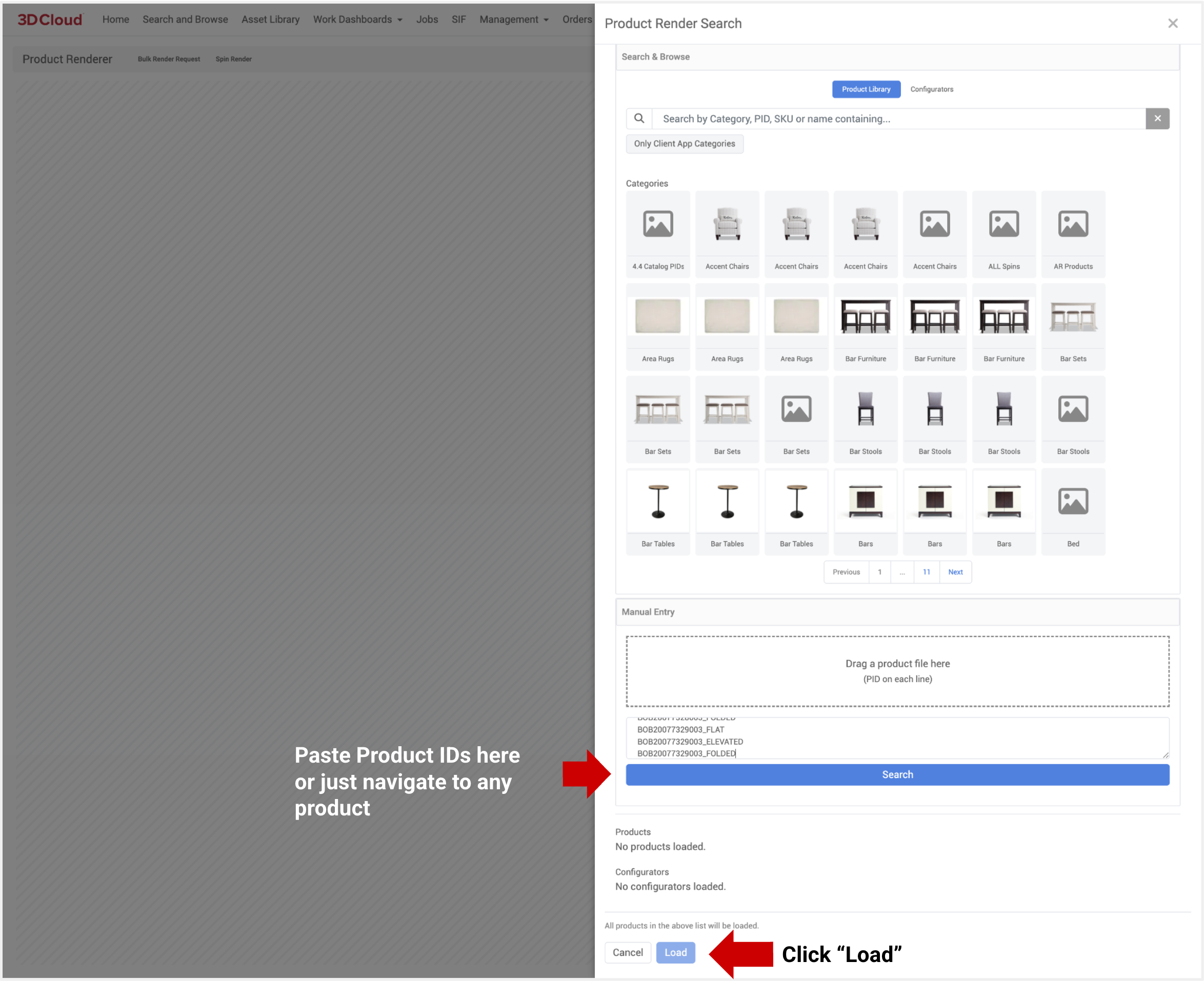
On Product Render view, you can select an existing preset, or adjust your camera and lighting settings under “Advanced Options”.
.png)
Existing Preset Selected
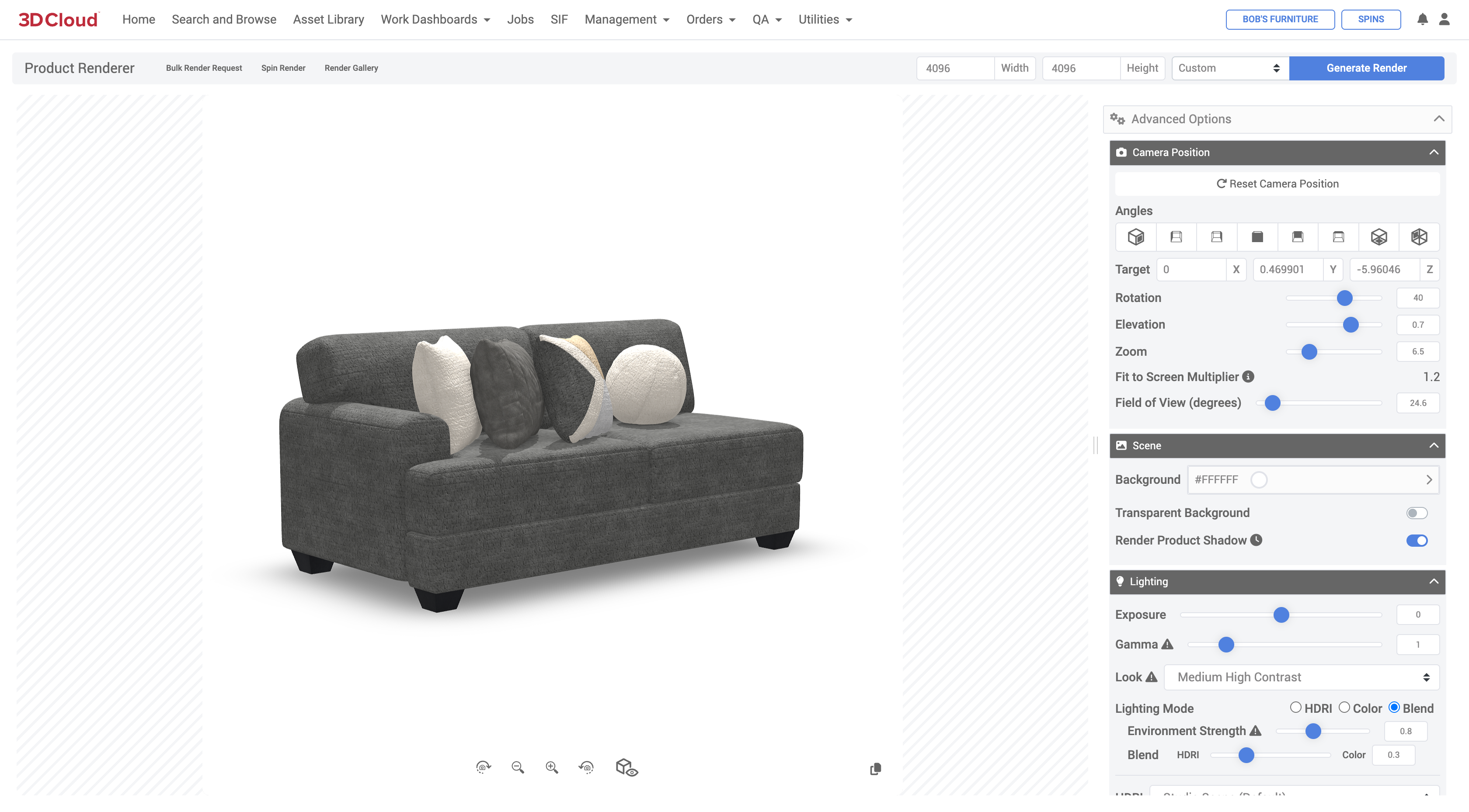
Adjust Advanced Options as needed
The preview window shows the camera and product position.
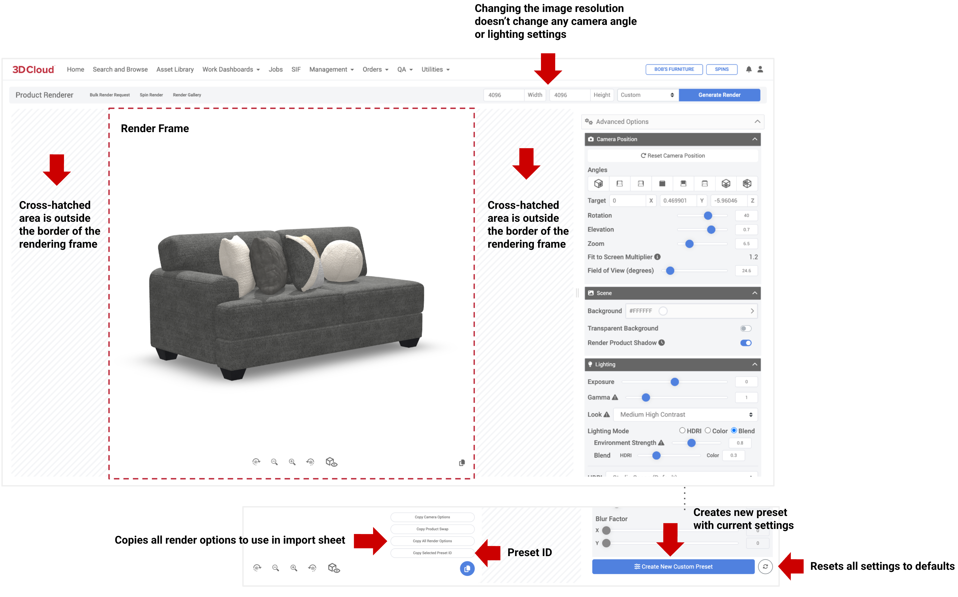
When setting presets, be aware of the Fit-to-Screen Multiplier is greater than 1.0 to avoid renders cutting off the product.
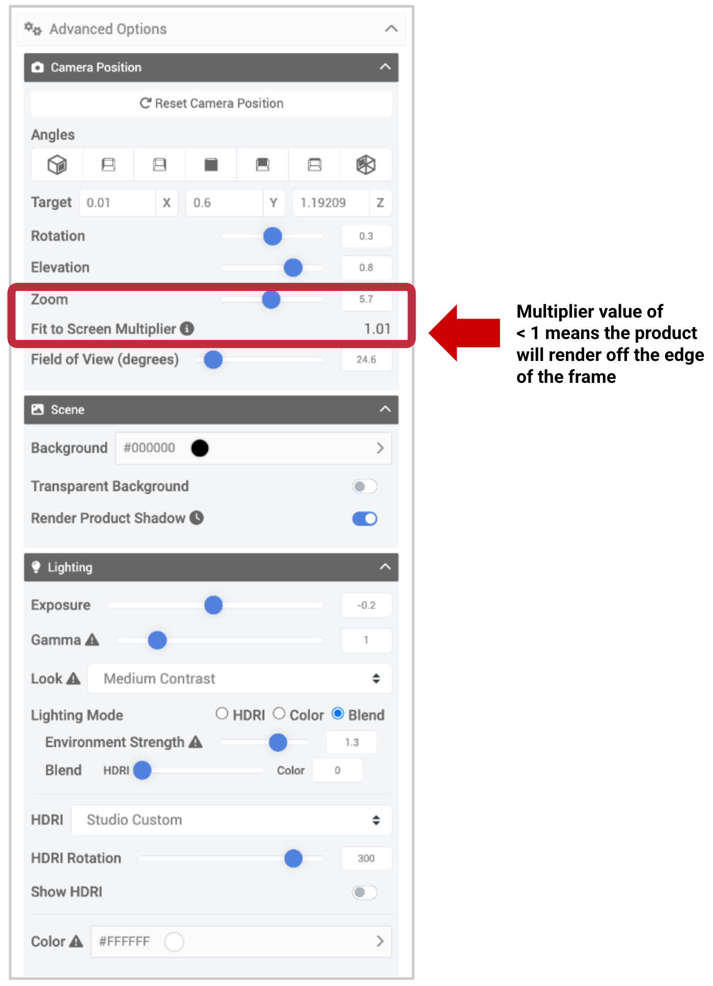
Click on Bulk Render Request. Select the “Click to import a bulk render request” button and select your .xlsx sheet or drag and drop the xlsx file in the dotted input box.
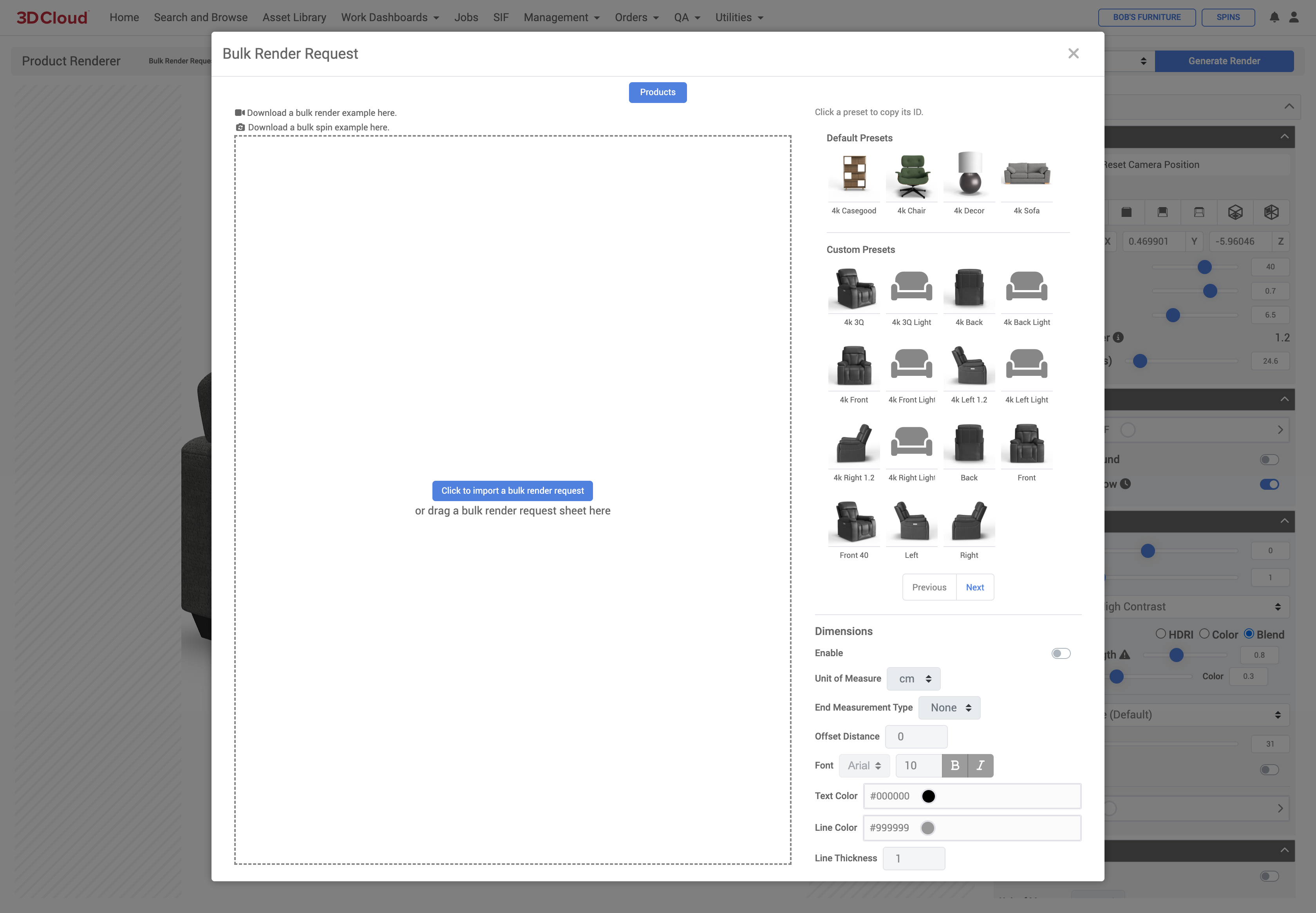
A confirmation window shows all items in the bulk request.
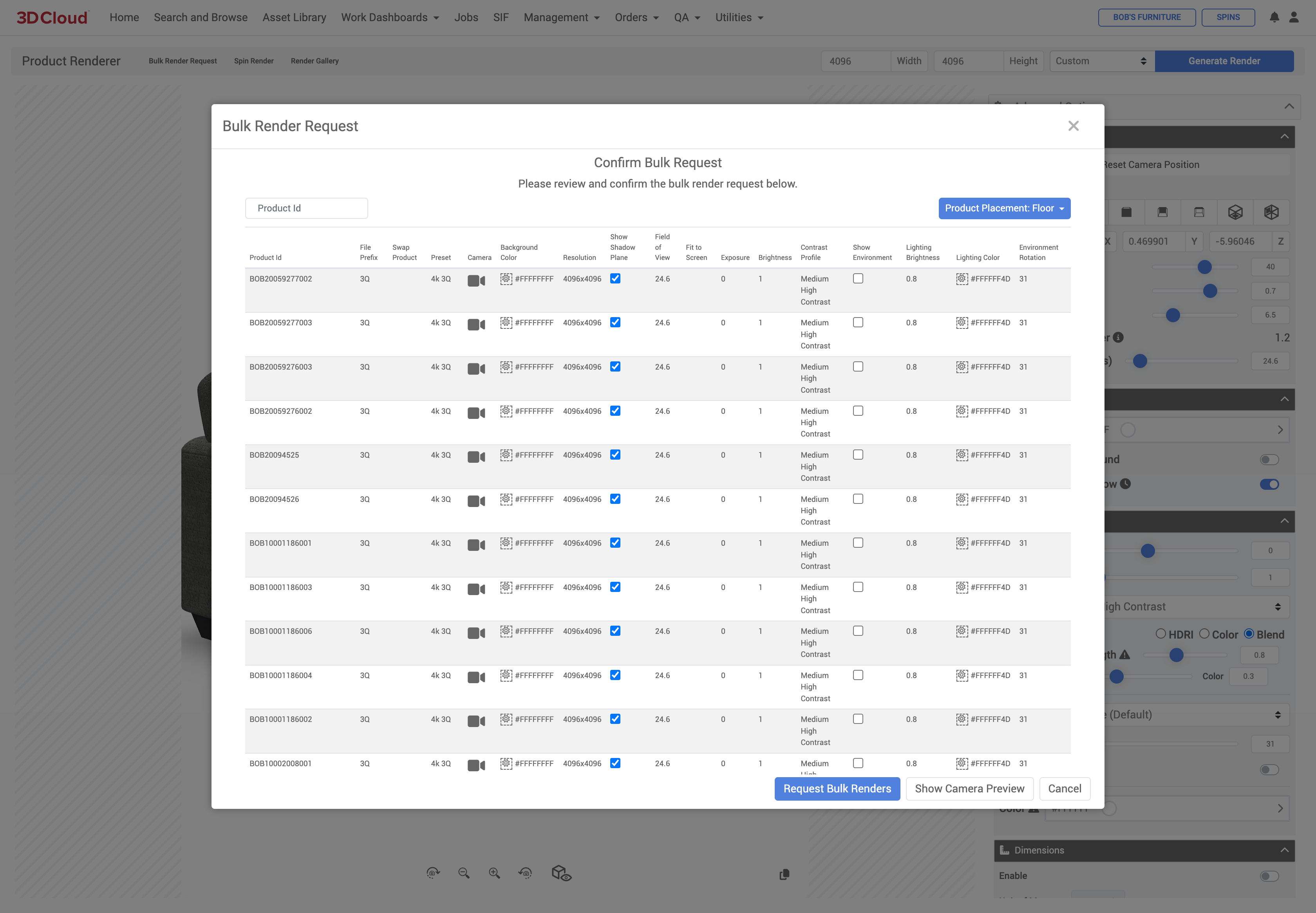
Click the “Show Camera Preview” button to check your crops. It can take up to 1 min per 50 products to load the preview.
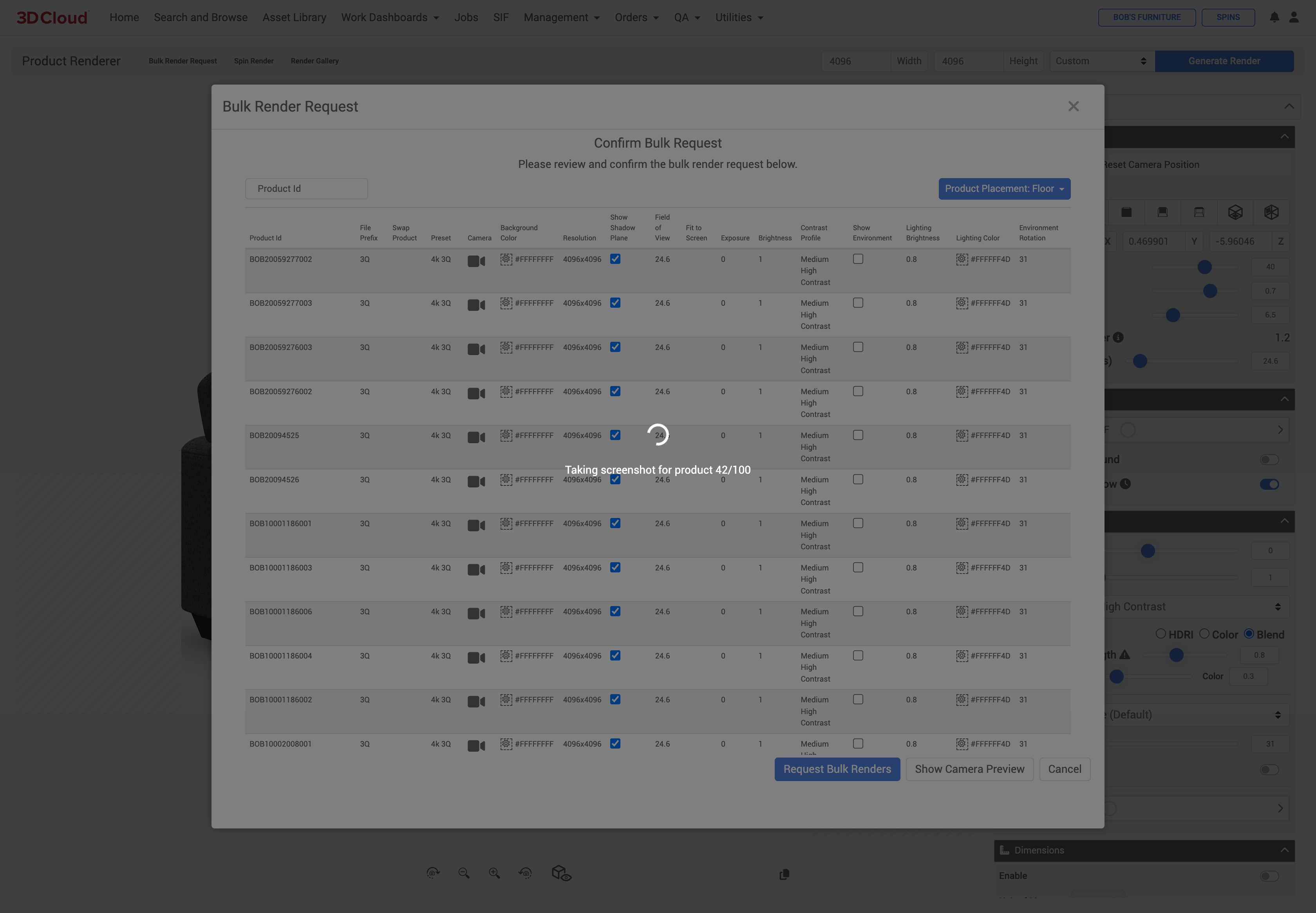
Check the preview and adjust any abnormalities with overrides in your bulk render sheet.
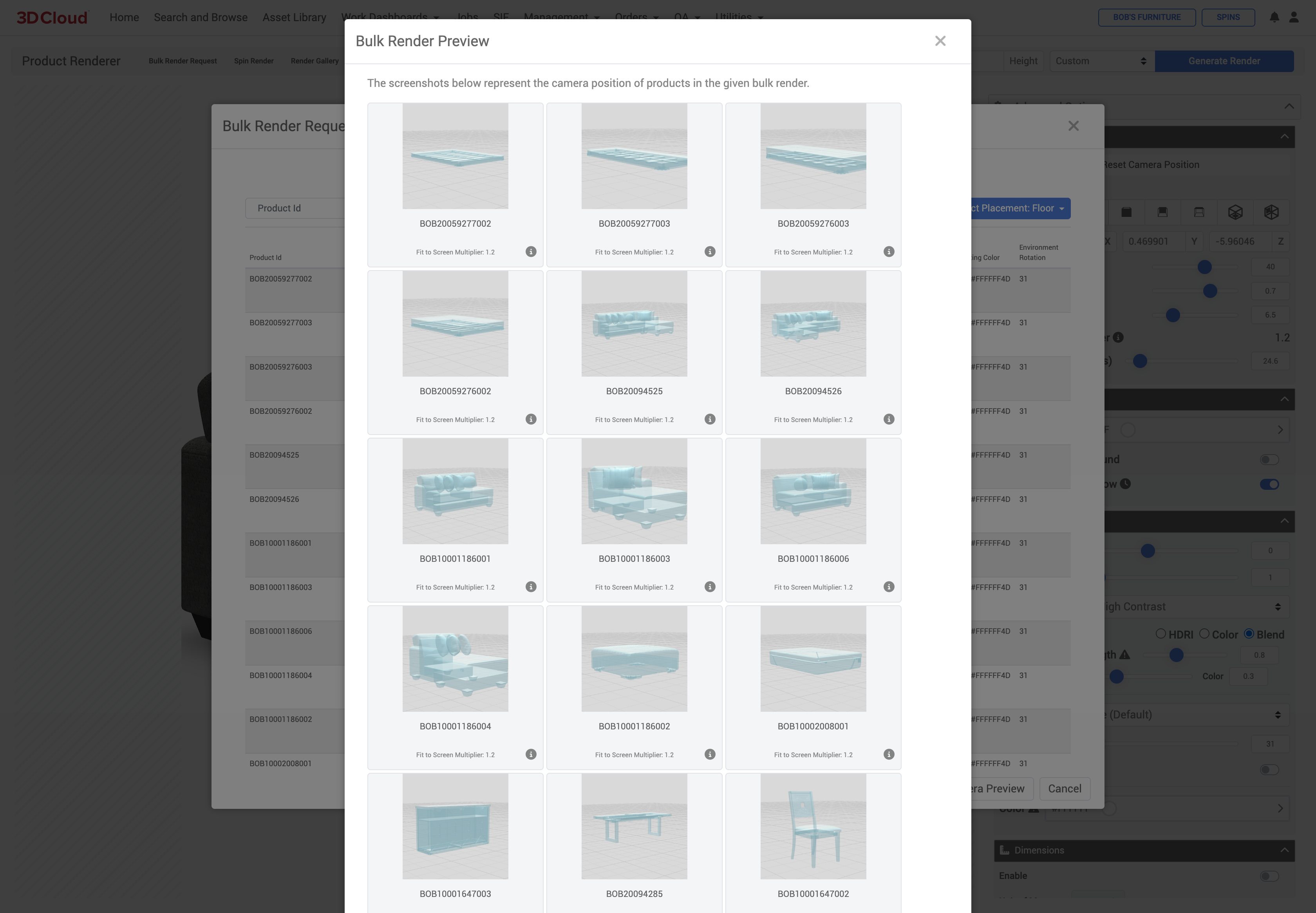
Creating an override. If you are using a preset on a product (even with Fit-to-Screen on the preset) and the camera preview is not appearing as expected, you can exit the camera preview, load that Product ID into the Product Render page, select the preset and then make camera or product adjustments. Click on the Copy icon under the product viewport and use the “Copy All Render Options” button to copy and paste into the desired sheet row.
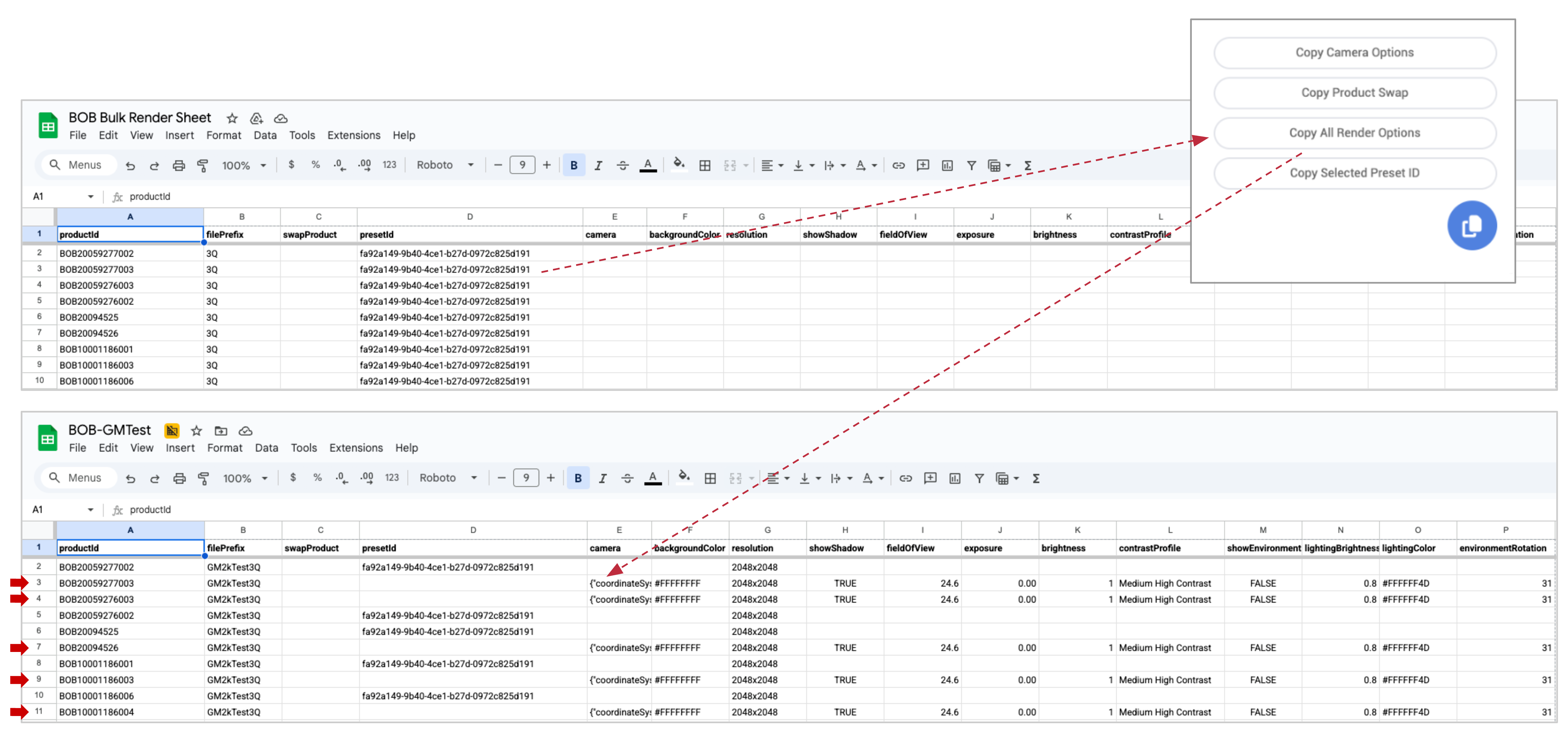
Products that may need an override to fit into the render frame are indicated with red arrows in the screenshot examples below. You can see that the products are extending outside the viewport/canvas.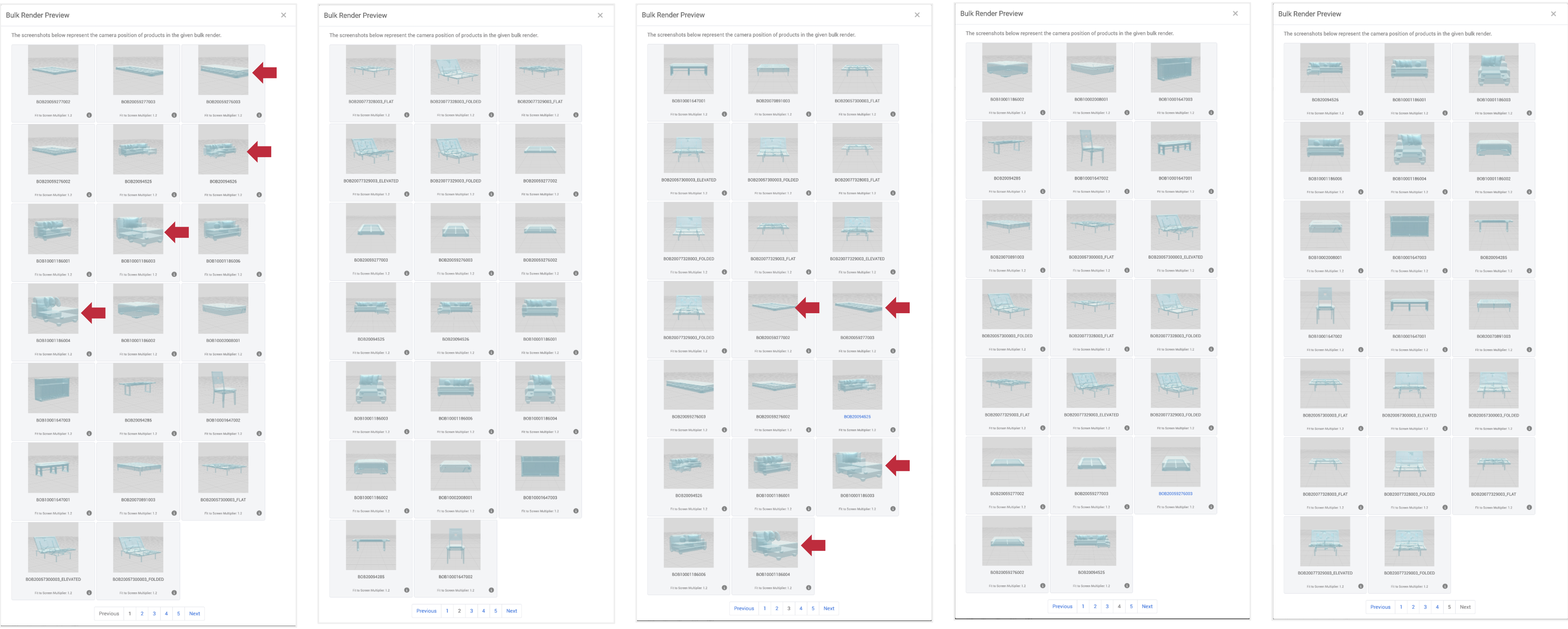
After adding “override” rows for the offending products to the bulk render sheet, reupload the sheet and click the “Show Camera Preview” again. The products are now fitting in the render frame shown in the Camera Preview. You are now ready to submit the bulk render job.
.png)
Make sure to select the Product Placement option for the bulk request (“Floor” or “Wall and/or Ceiling”) and click the Request Bulk Renders button to submit the job.
.png)
NOTE: Do NOT close your browser window at this point until the job is complete.
After your bulk render request is complete, you will receive an email notification with the subject line: “3D Cloud - Render Complete”
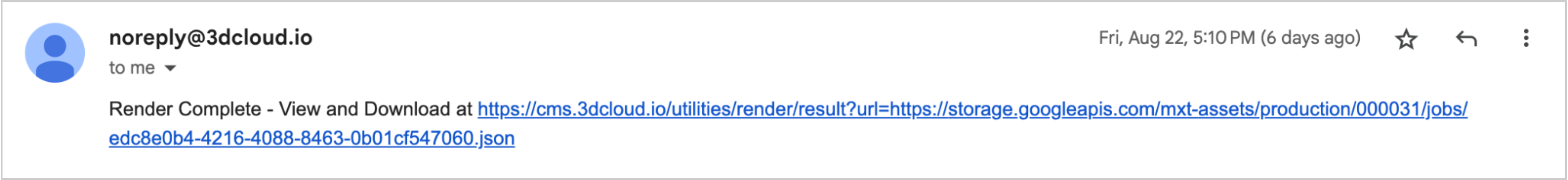
Clicking the link will take you to a download page, where you can select to download all files—specify “File Prefix” only if you want the downloaded files to have the filePrefix (filename) from your bulk render sheet.
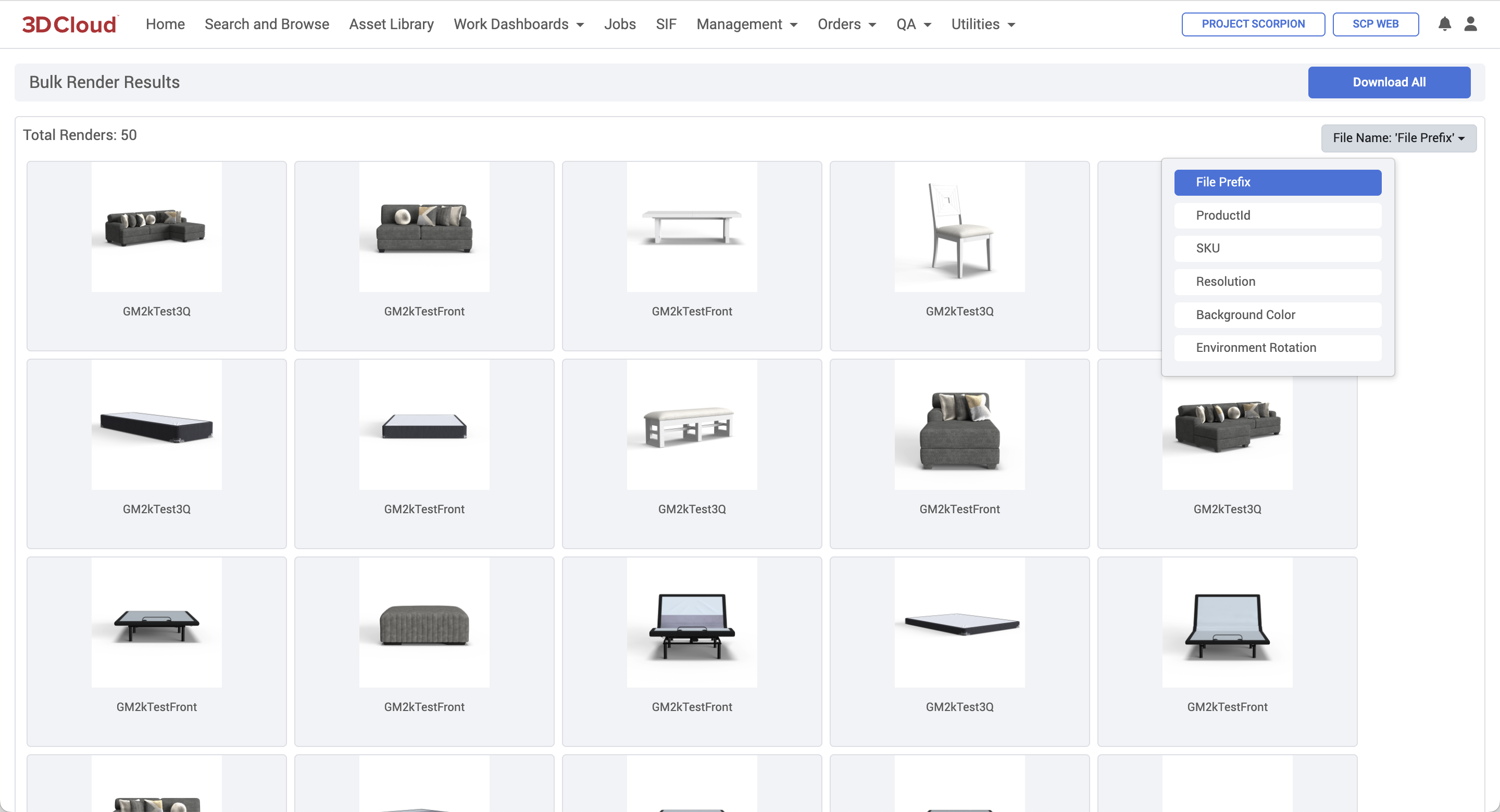
Spin Renders
A Spin Render generates 33 images of a product, rotating the camera counter-clockwise in 12° increments around the object, plus a top view. It can be accessed on the Product Renderer Page next to the page title.
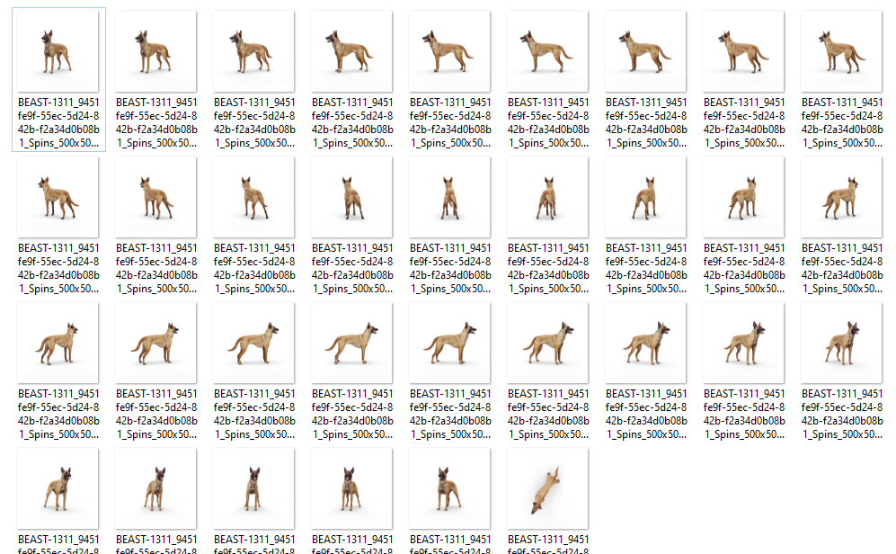
Step-by-Step Instructions
Load your desired Product(s) and press the “Spin Render” button in the Product Renderer title bar to switch to spin render mode.
.png)
This will change the render Advanced Options to read-only.
Note: All spin render options (except for Background Color) are controlled by/inherited from the Client App Config file (which cannot be edited through the AMS). To adjust your Client App Config settings, coordinate this with your 3D Cloud account team.
Click the “Generate Spin” button on the Spin Render mode page.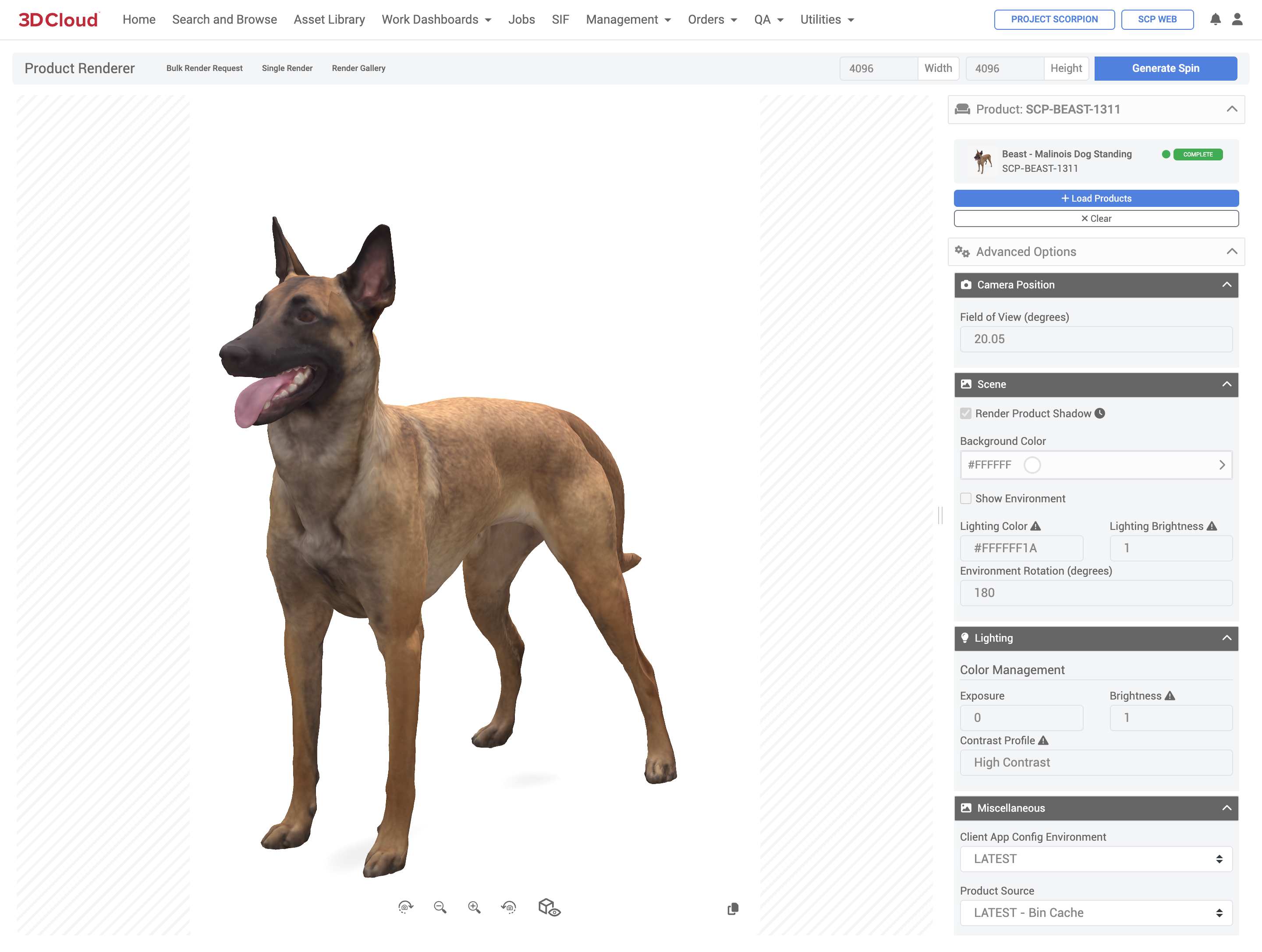
While your render is processing, you can view it’s current status for all 33 spin images by clicking the notification bell at the top right of the AMS window. Your spin render will not be visible in the Render Gallery until at least 1 image has been created in the spin. If you visit the Render Gallery before the first image is created, you won’t see any spins.
Note: It can take up to 19 hours generate a spin render depending on the complexity of the 3D model, because it is run on a slower Cloud node. You will not receive an email notification for Spin or Bulk Spin Render requests.
.png)
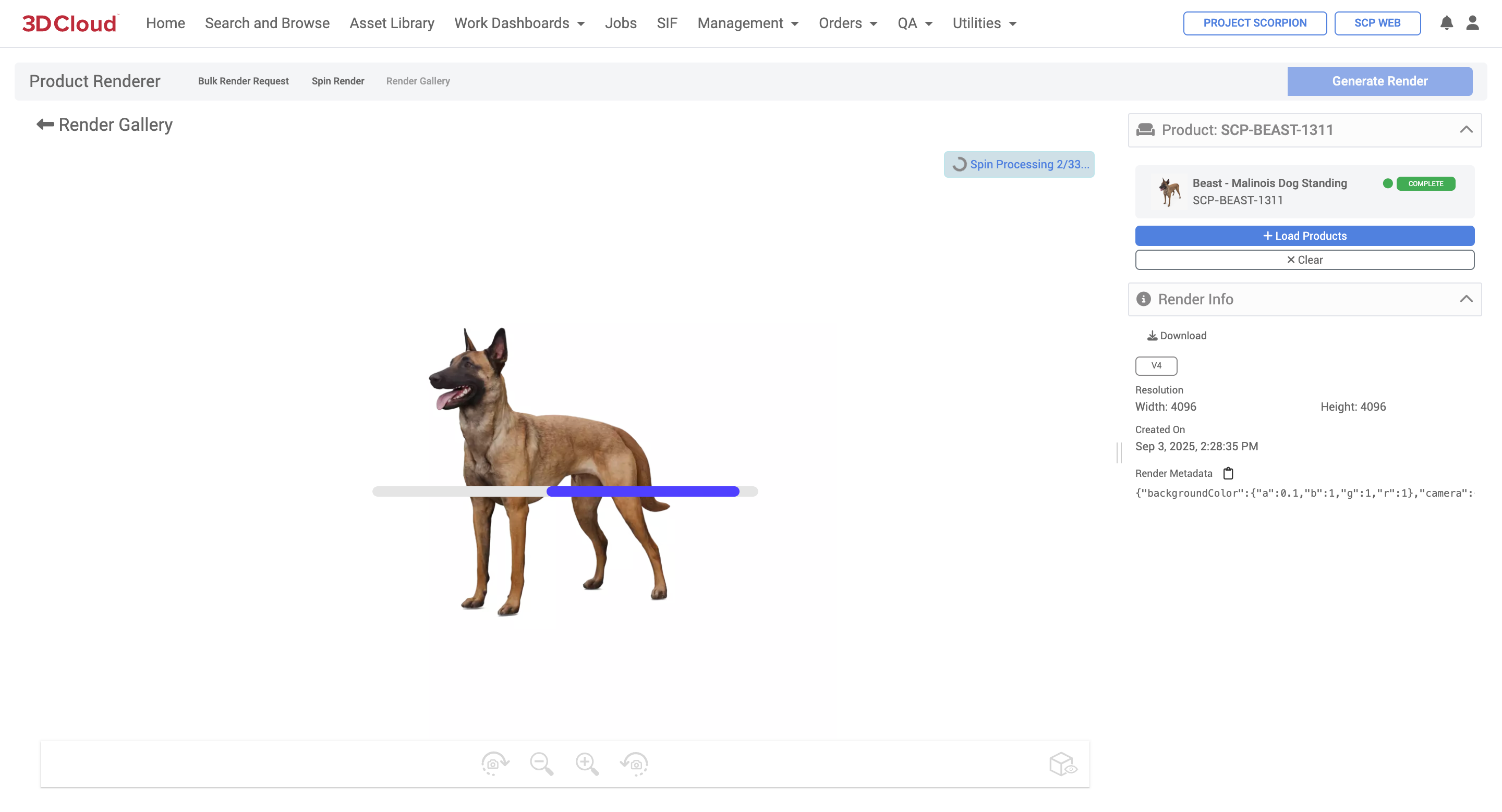
Bulk Spin Renders
Multiple product spin renders can be made using the “Bulk Render Request” functionality but with a different .xlsx template sheet tailored for Bulk Spin Renders.
Navigate to the Bulk Render Request modal window on the Product Renderer page.
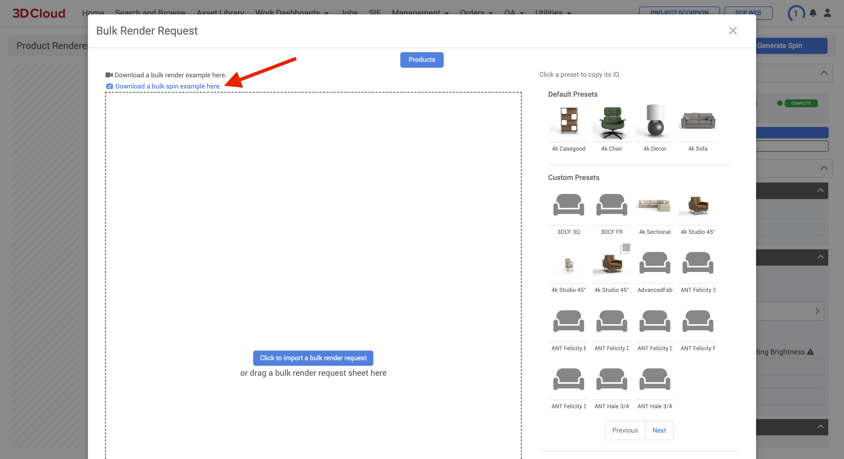
Download and fill out the example-bulk-spin-request.xlsx template. Make sure “spin” is specified in the “camera” column D. Note that Preset IDs are not present on the Bulk Render Spins sheet, since settings are controlled by the Client App Config.
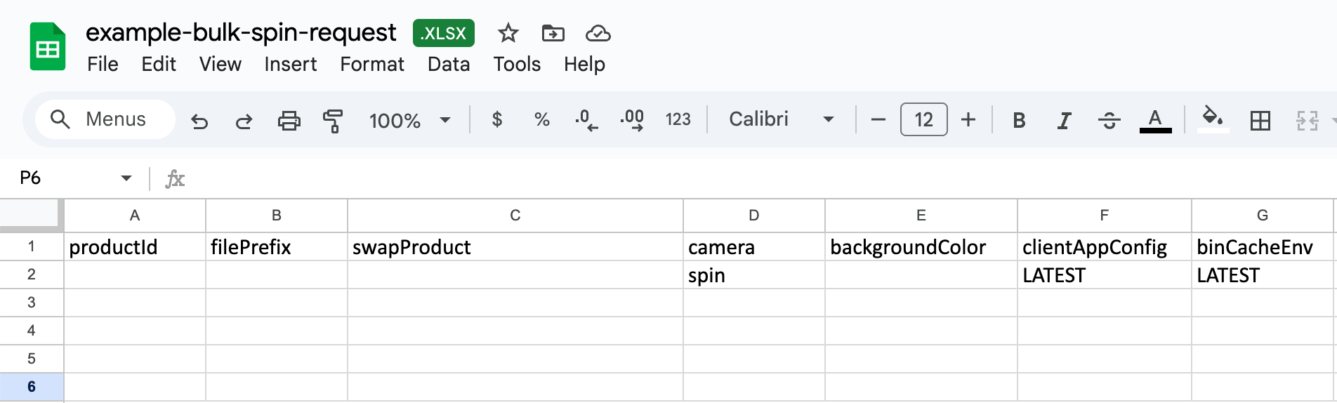
Click the “Click to import a bulk render request” button to import the bulk spin sheet or drag and drop it onto the dotted input window. A Bulk Render Request confirmation modal will open, allowing you to see one final snapshot of your render request prior to submission.
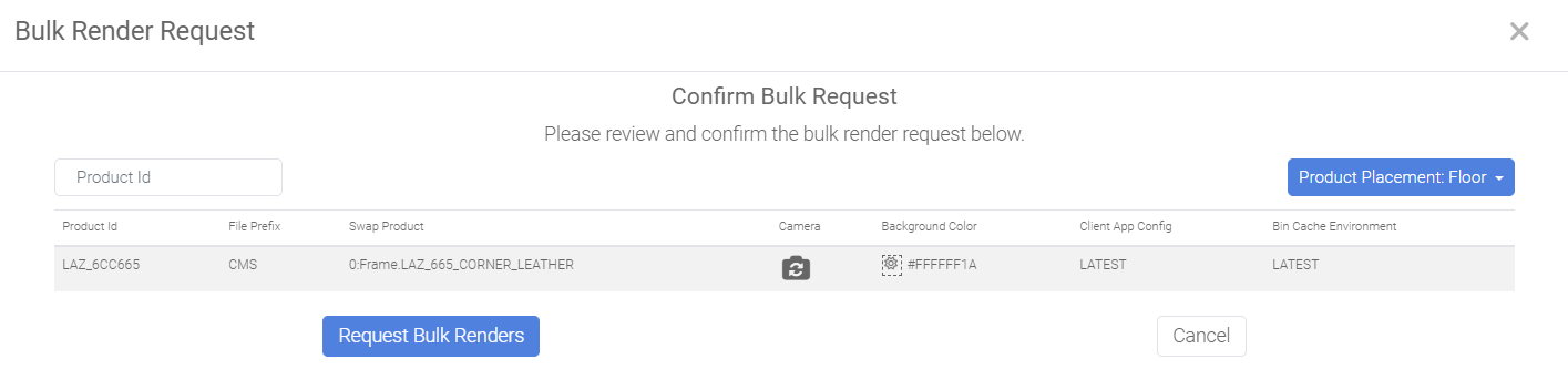
Note: If you select Product Placement: Wall and/or Ceiling a warning will appear indicating Shadow Planes will be disabled for Wall and Ceiling products.
Click the Request Bulk Renders button.
Note: It can take up to 19 hours per product spin render, because it is run on a slower Cloud node. You will not receive an email notification for Spin or Bulk Spin Render requests.
Product Configurator Render
To generate an HD render of an individual product configurators, follow the steps below:
Access Product Configurator via Utilities → 3D Product Configurator.
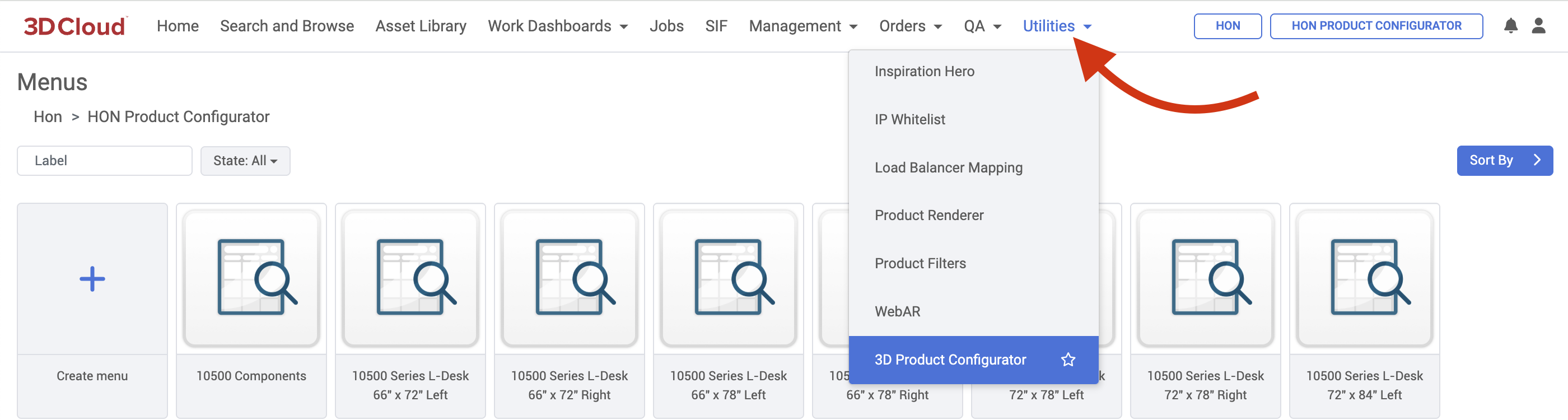
Navigate to the Product Configurator you want to render.
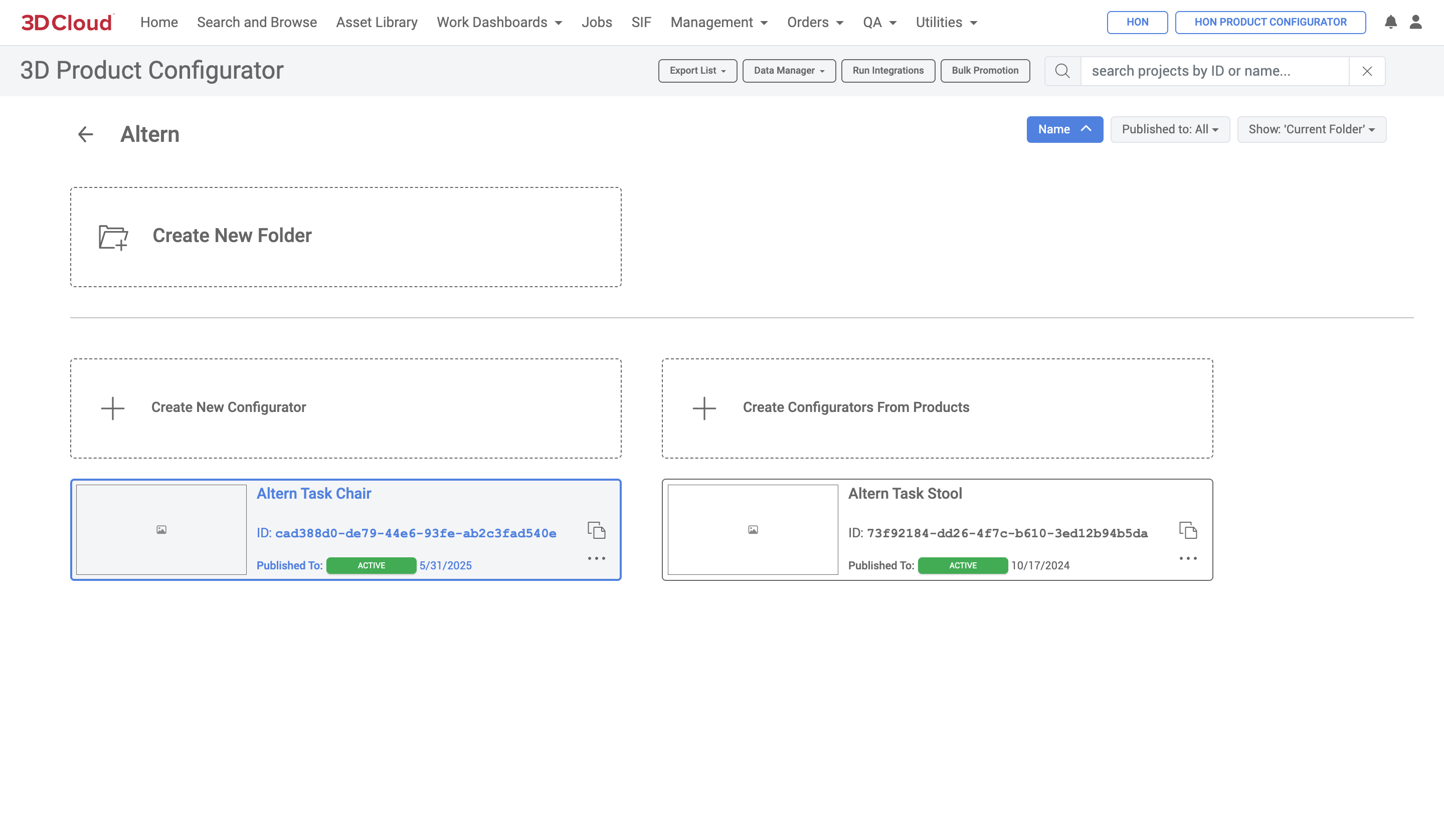
Click the “Generate Renders” button
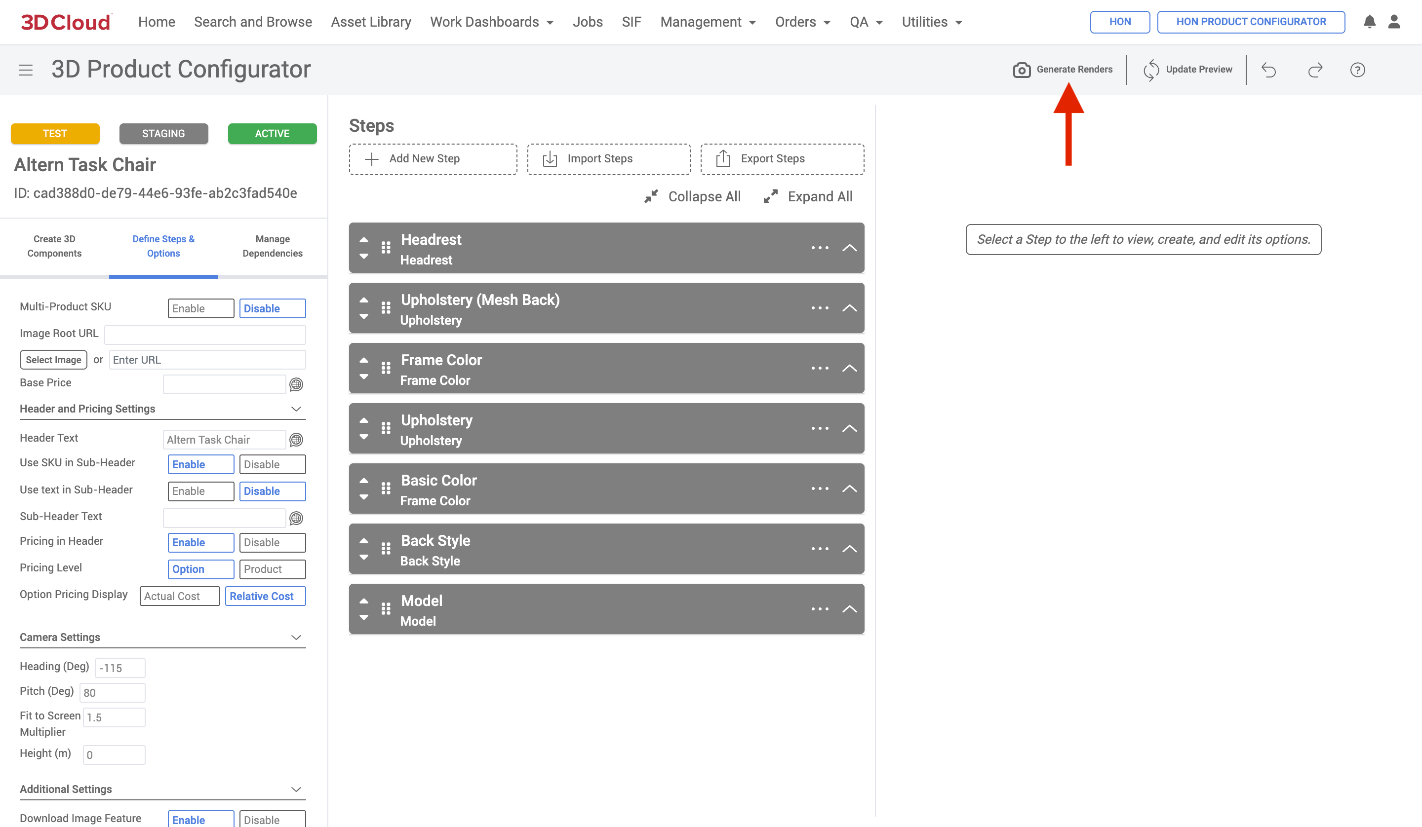
A Product Renderer page will be shown, with the configurator loaded into the 3D preview area.
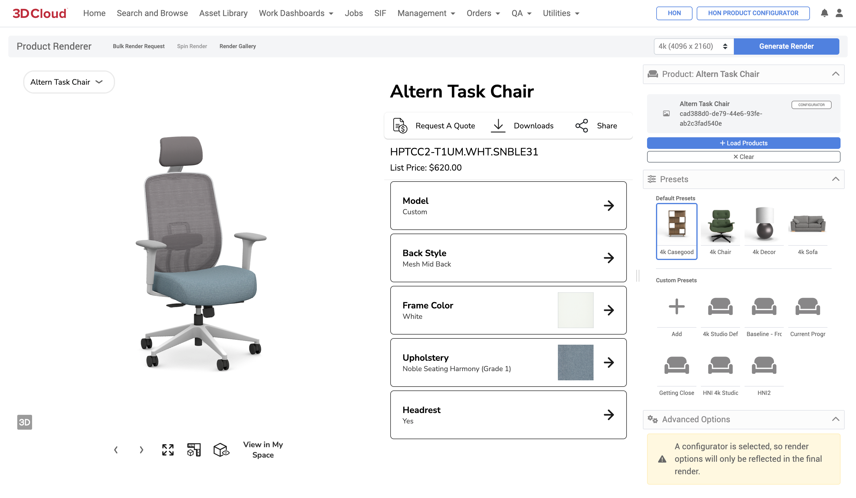
Presets can be selected for use in your render, as in Single Product Renders. Adjust your Advanced Options settings to your liking and click the “Generate Render” button.
Note: Advanced Options for Product Configurators are the same as in Single Product Renders, but do not include Camera Position controls. Render options are also not reflected in the Configurator preview, so running test renders is required to preview your results should you want to create/adjust your custom preset settings.
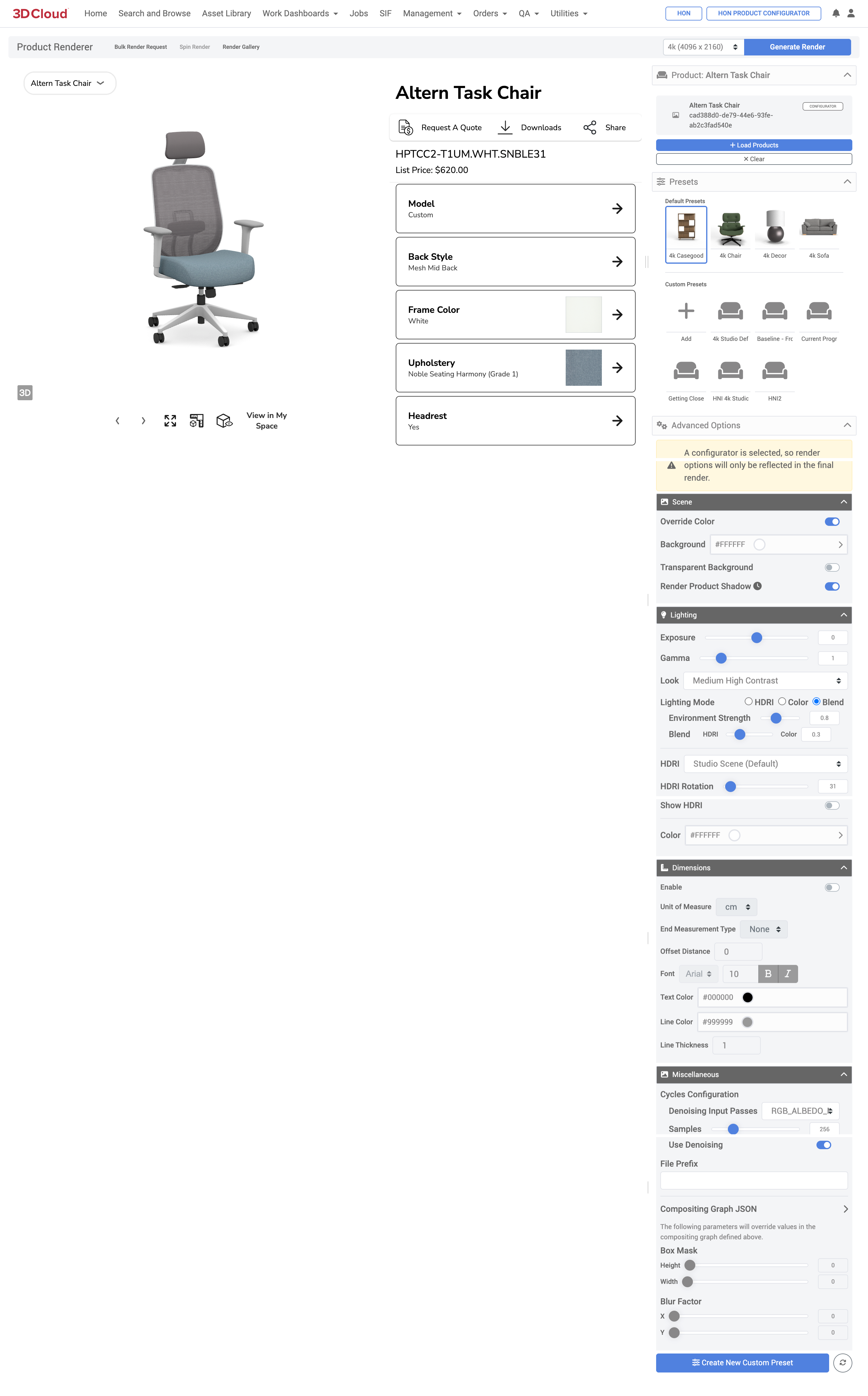
Render status messages and notifications are the same as Single Product Renders. When render jobs are completed, you will receive email notifications with download links, or can watch the notification bell area for a completion message. Final renders are stored in the Render Gallery of the associated product configurator.
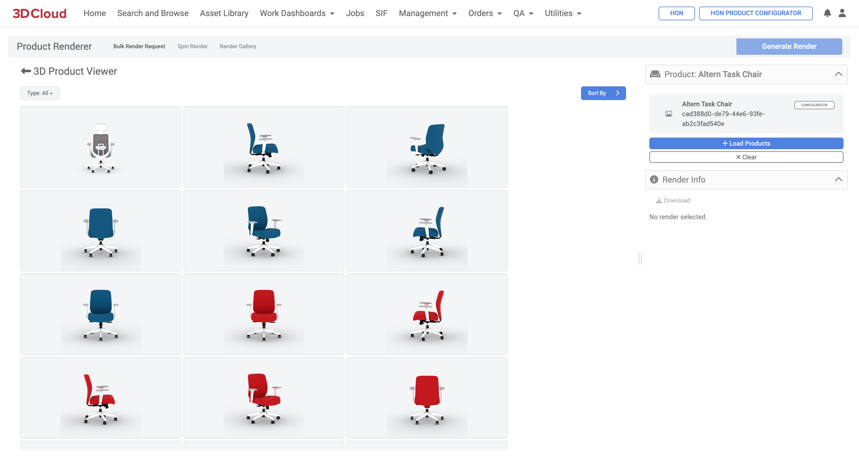
Product Configurator Bulk Render
Bulk requests from a Product Configurator can be made via the “Bulk Render Request” button.
To generate an HD render of an individual product configurators, follow the steps below:
Navigate to the Product Configurator you want to render as in the single Product Configurator Render scenario.
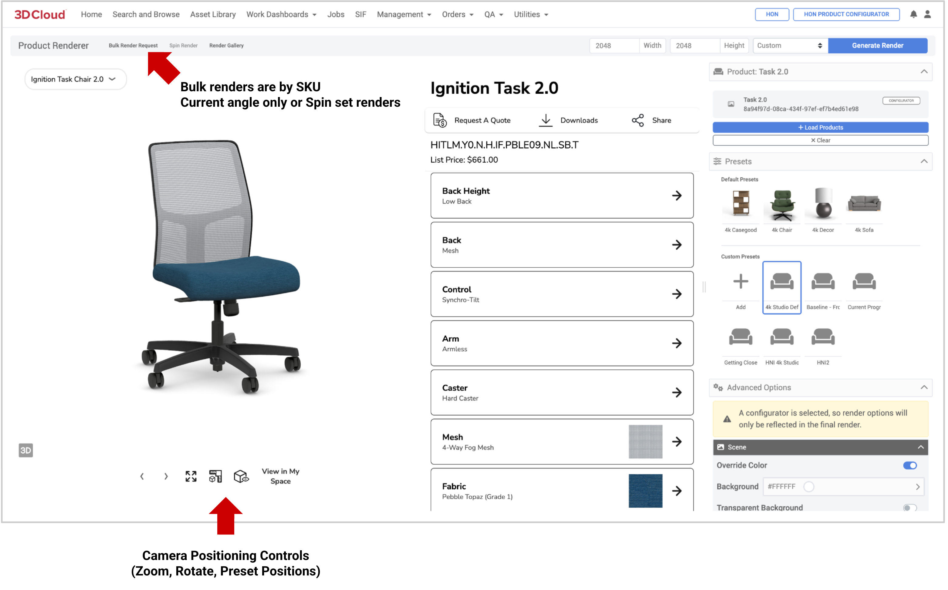
After clicking the button, the Bulk Render Request modal window appears, where you can submit a list of SKUs (one line each) for bulk renders.
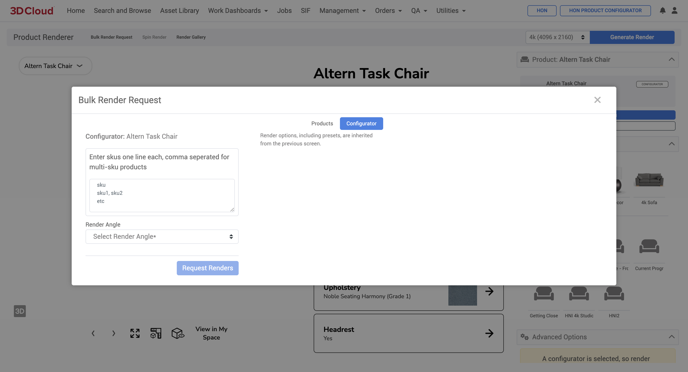
The render angle options for Bulk Render Requests of Product Configurators include:Current View Angle Only
All Render Spin Angles
Click the “Request Renders” button to submit your render job.
Render status messages and notifications are the same as Single Product Renders. When render jobs are completed, you will receive email notifications with download links, or can watch the notification bell area for a completion message. Final renders are stored in the Render Gallery of the associated product configurator.
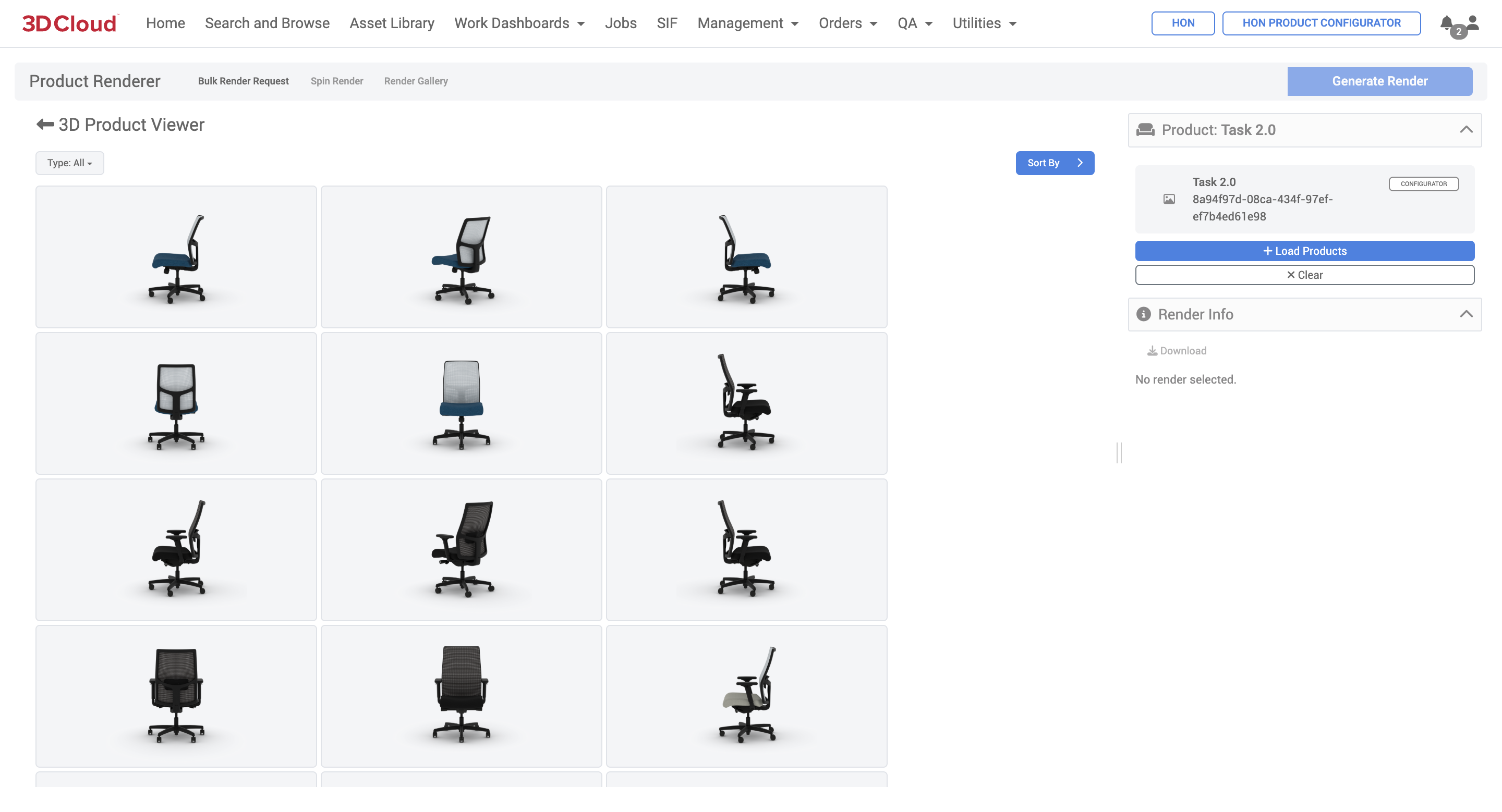
Multi-SKU Products
To render multi-SKU product configurators, each line in the Bulk Render Request modal window can contain all the SKUs in one line separated by commas (no spaces).
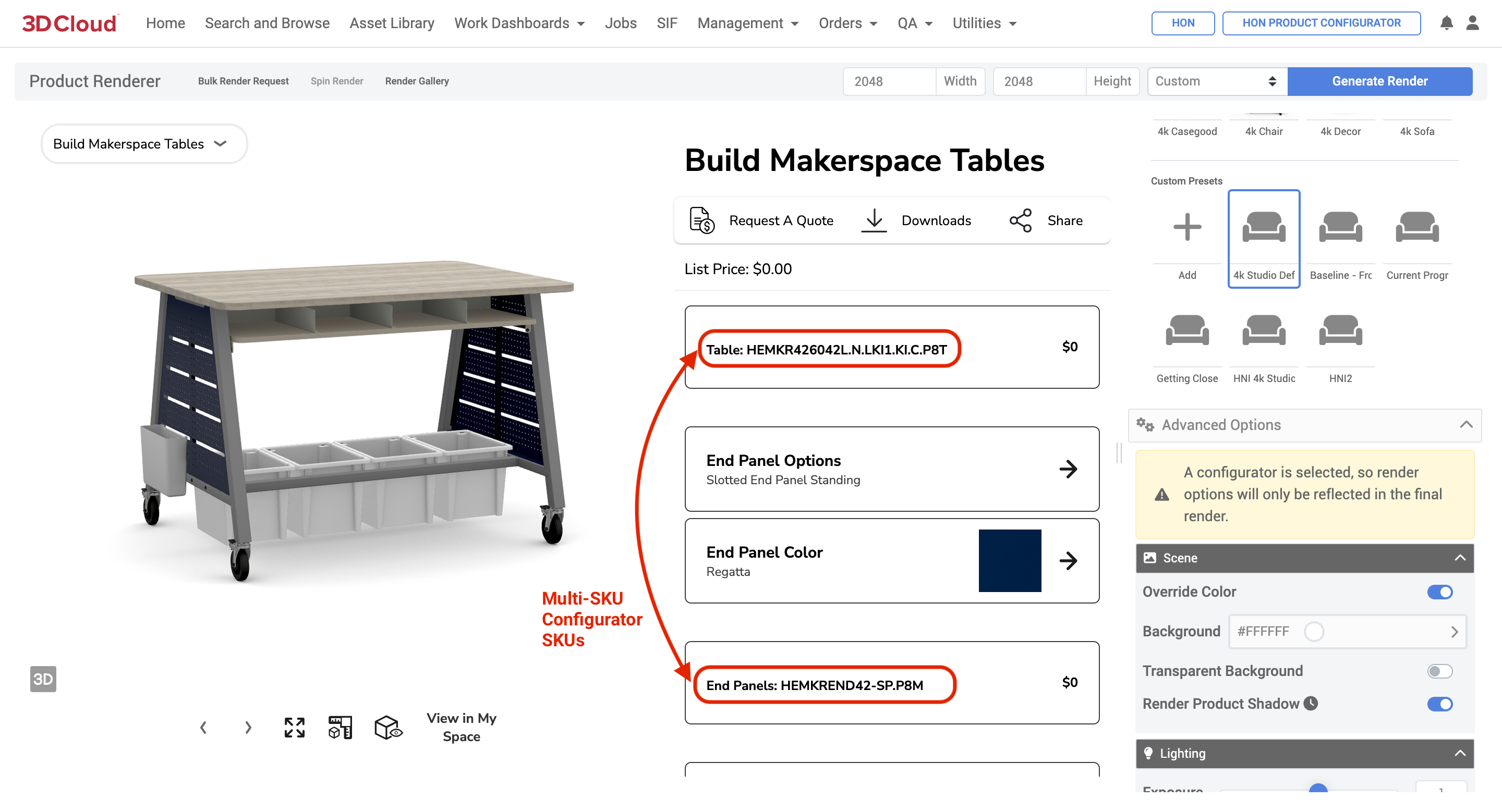
Example: Multi-SKU Product Configurator
.png)
Multi-SKU Product Configurator Render Request
_HEMKR426042L.N.LKI1.KI.C.P8T,HEMKREND42-SP.P8M,HAESS.DW,HFMBIN12,HEMKRSHELF.LOFT.LOFT,HEMKRDIVIDER.LOFT(1).png)
Multi-SKU Product Configurator Render
Product Configurator Spin Render
Product Configurator Spin Renders are created by selecting the “All Render Spin Angles” dropdown option on the Bulk Render Request modal window.
Note: The render spin angles are determined by the Client App Config settings.
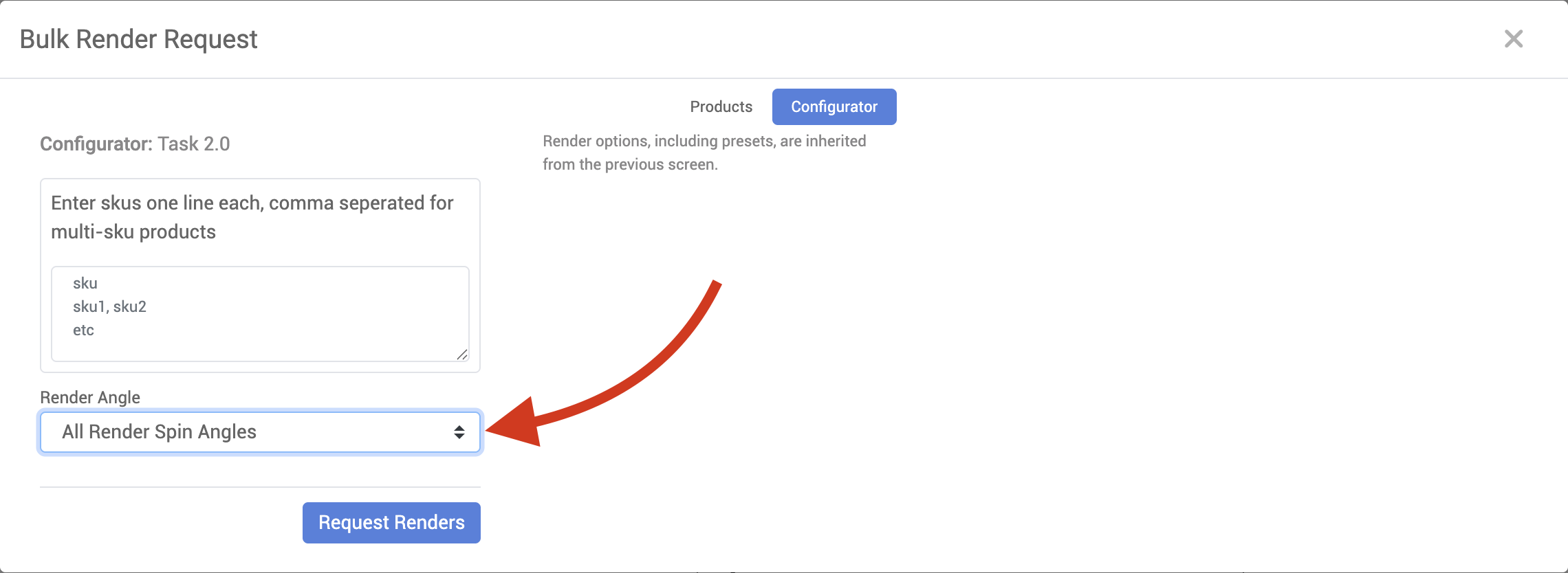
Product Configurator Rendering On Demand
The customer-facing view of 3D Cloud’s Product Configurators have a feature to request and download HD Renders at preset angles.
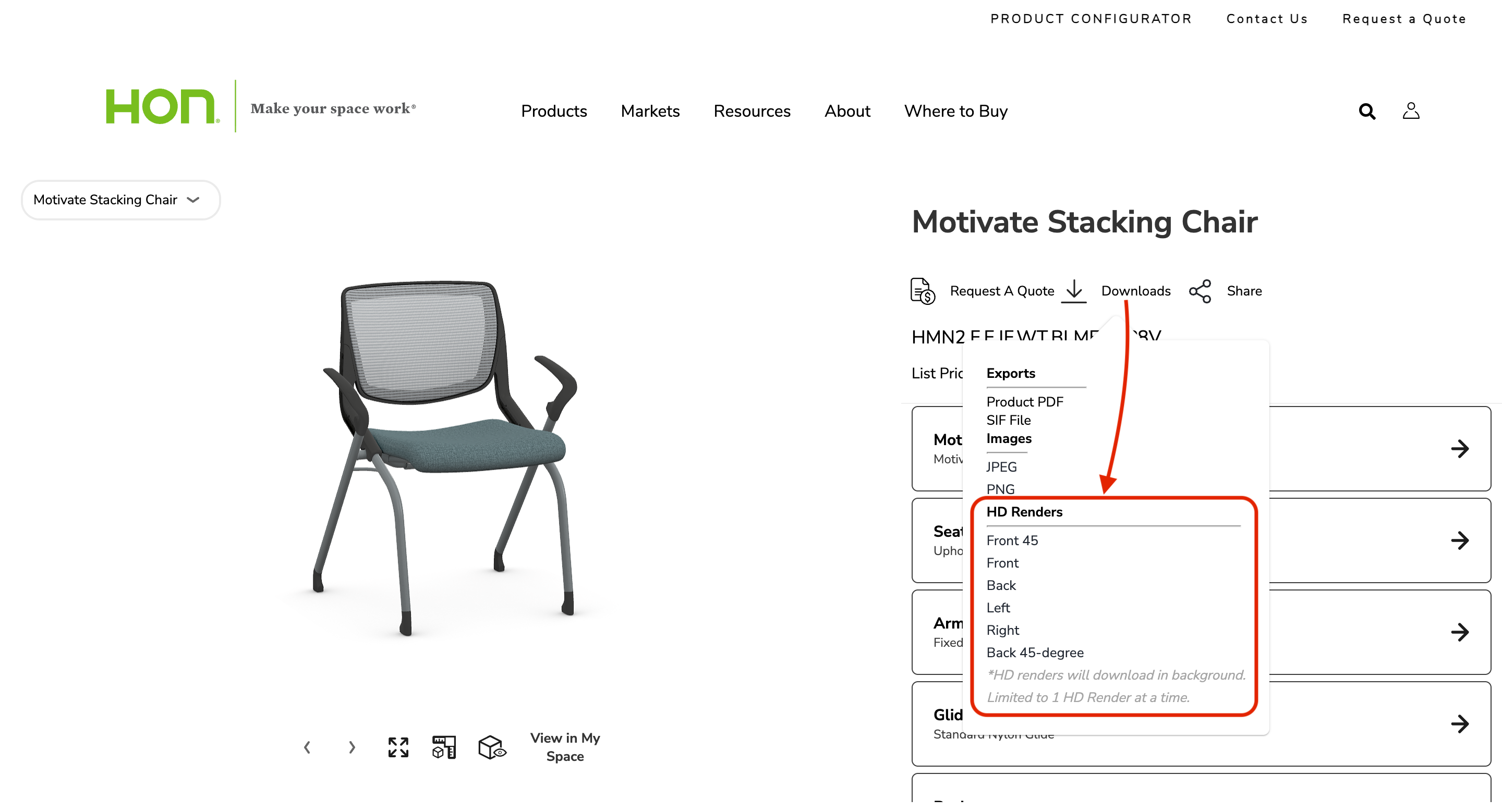
Download HD Renders feature
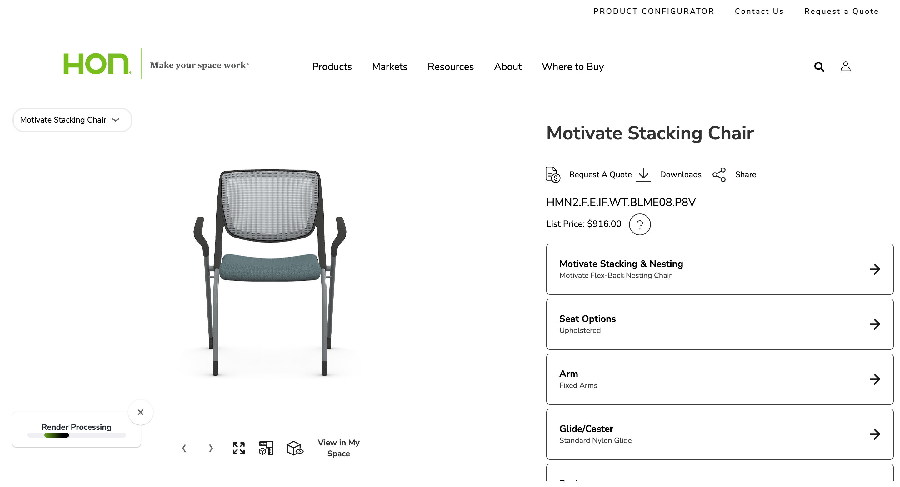
On Demand Render Processing message

HD Render Complete message
Clicking on “Download HD Render” will download a final render to your computer.
Product Configurator On Demand Final Render
Lifestyle HD Renders
Inspirational Lifestyle HD Renders are possible using the 3D Cloud Room Planner. For guidance on how to use the Room Planner to generate room scenes like the ones below, refer to our Room Planner User Guides or your 3D Cloud Room Planner Training advisor.
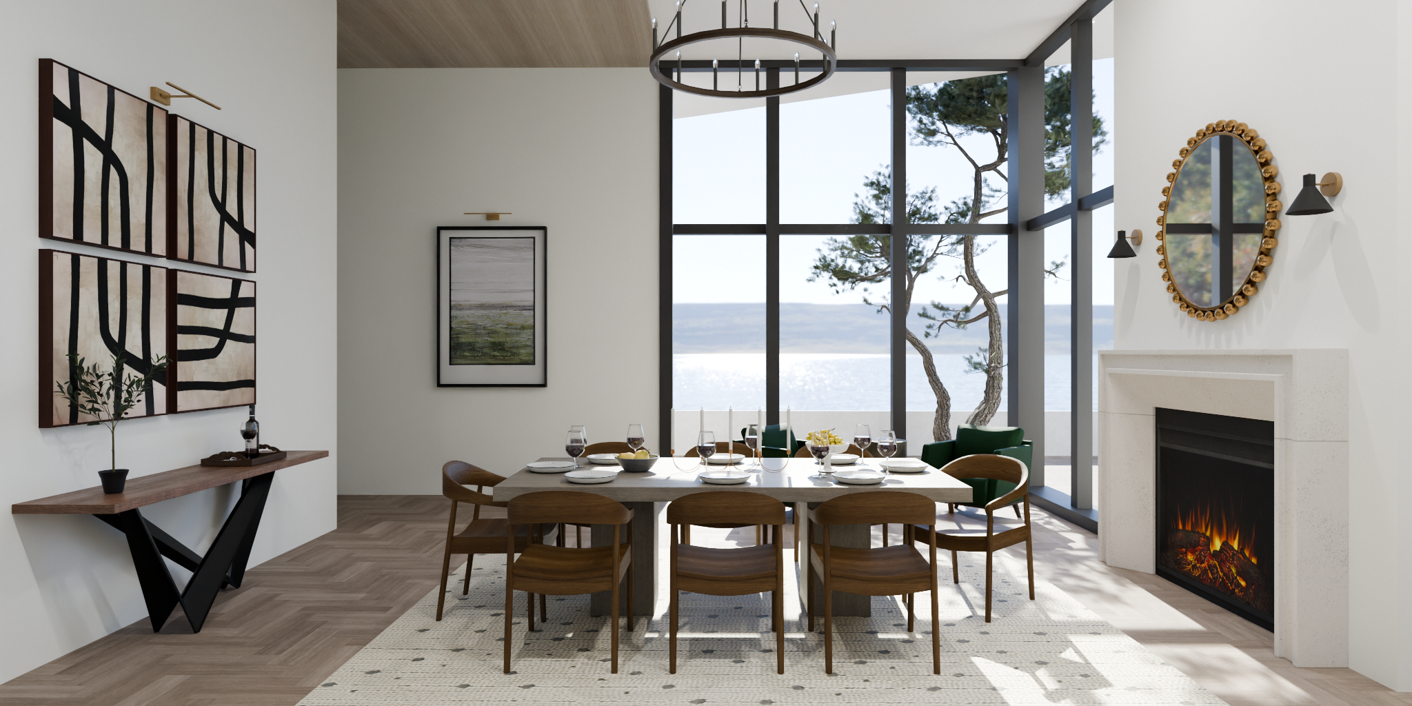
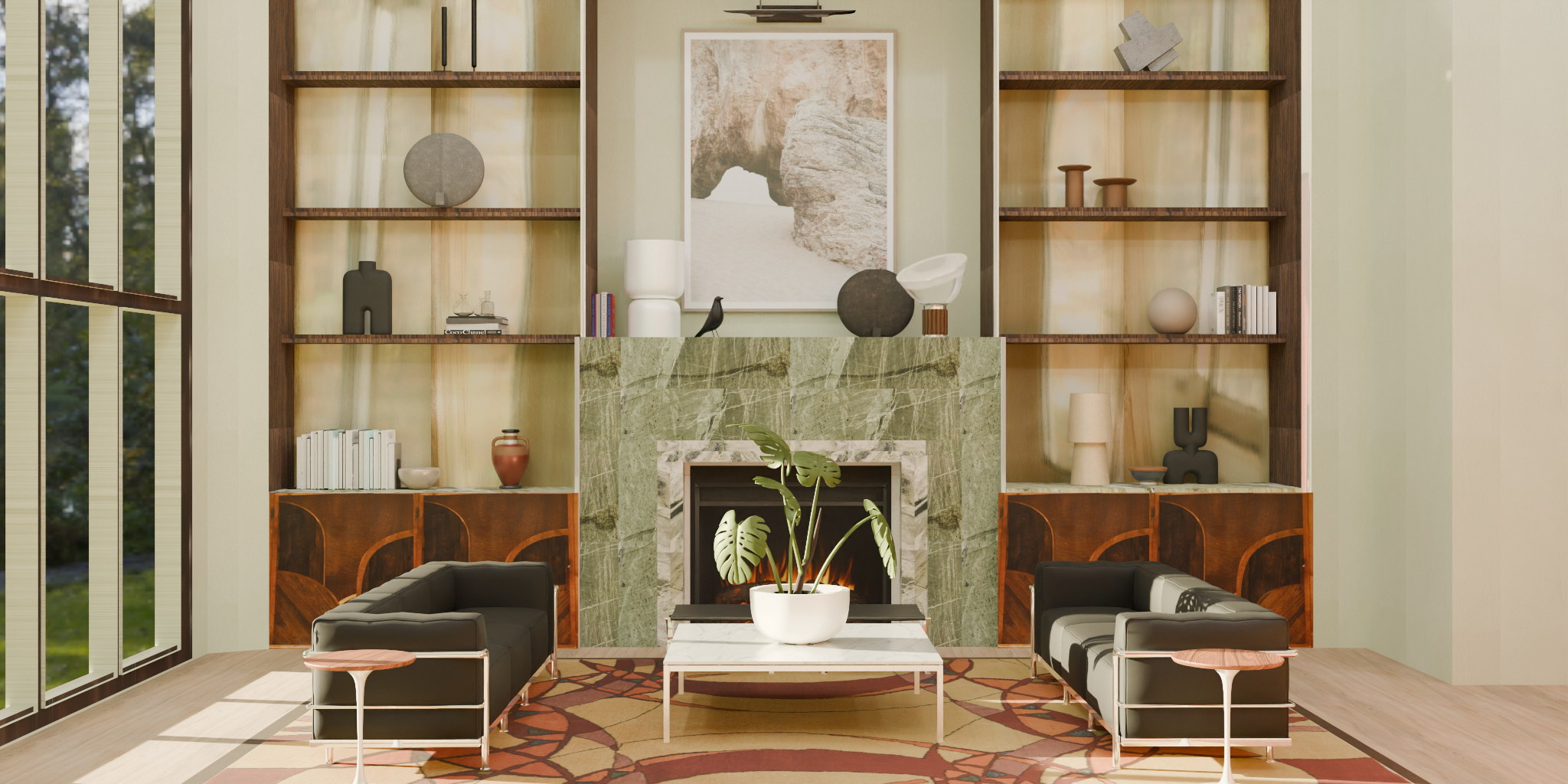
Product Filters
Product Filters are similar to product categories - they allow the grouping of similar products by a common attribute. For example, a filter named “Color” might contain filter options “Red”, “Blue”, and “Green”, each of which contains products of that particular color. This utility can be accessed via Utilities → Product Filters.
Prerequisites
Ensure that a 3D Cloud AMS Administrator has assigned you the “Product Filter Browser” feature in order access this utility, and “Product Filter Manager” to perform edit operations.
Browsing Product Filters
Product filters can be browsed similarly to Inspiration Filters/Options. Navigate to Utilities->Product Filters to view filters defined for the selected client.
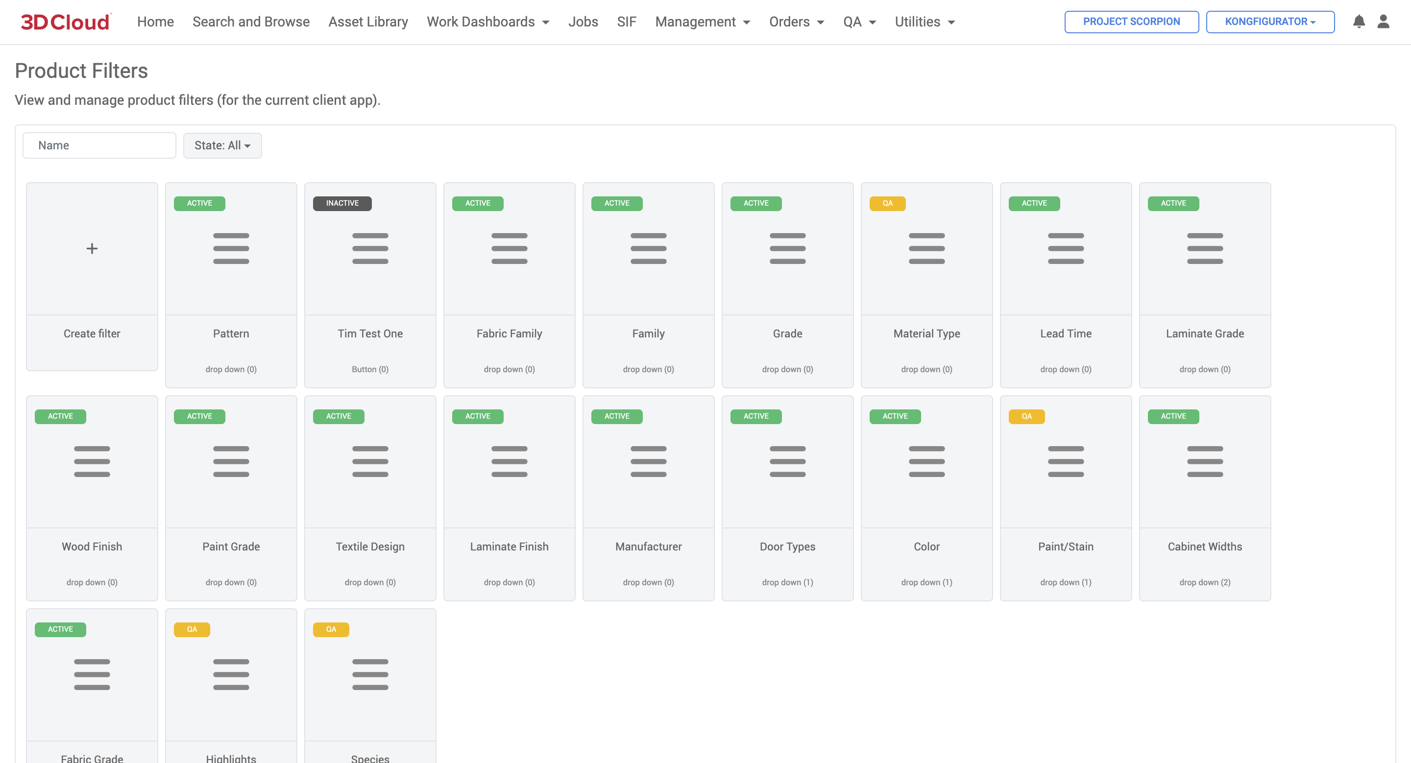
The number in parentheses under the filter name is the order number of that filter. Clicking on a filter will display all filter options belonging to that filter (think of these as sub-categories). Similarly, the filter option order is displayed in parentheses.
Note: Product Filters are scoped to the selected client, but Filter Options are assigned to a specific client app.
.png)
Products are assigned to filter options. Click on an option to view all of its currently-assigned products. Note that clicking on the product will navigate to the product detail page.
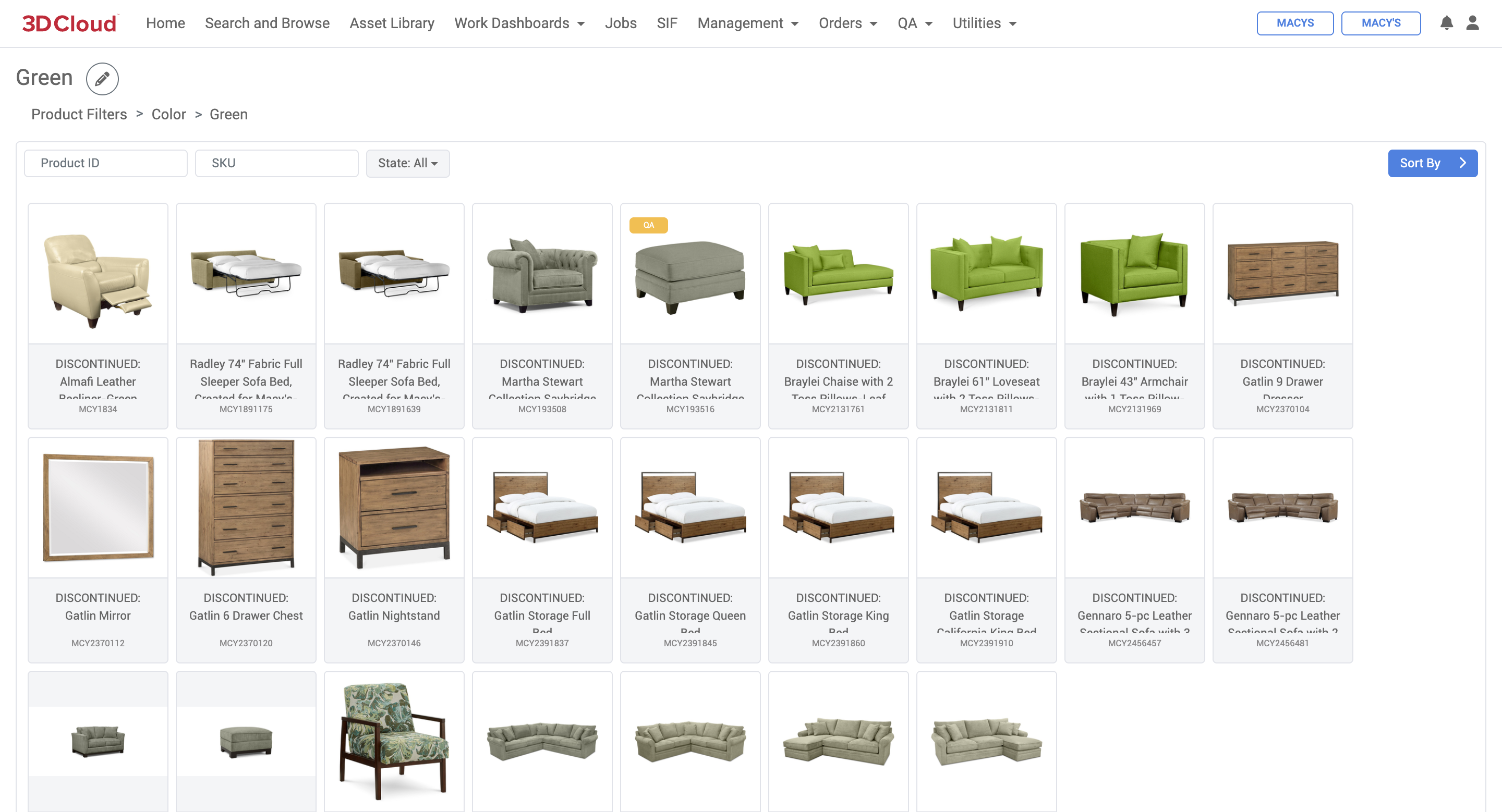
Creating Product Filters
Product filters can be edited by those with the appropriate feature assignments. To create a product filter, click on the “Create filter” button on the main product filter page.
.png)
Creating a New Product Filter
Editing an Existing Product Filter
To edit a product filter, click the edit icon on the top-right “tools” icon of an existing Product Filter card. A detail panel will display on the right.
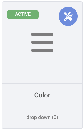
Basic product filter metadata can now be edited under the “Filter” tab. Options belonging to this filter can be viewed and/or removed on the “Options” tab. Users may also add options in bulk from this tab, rather than individually from the filter detail browser.
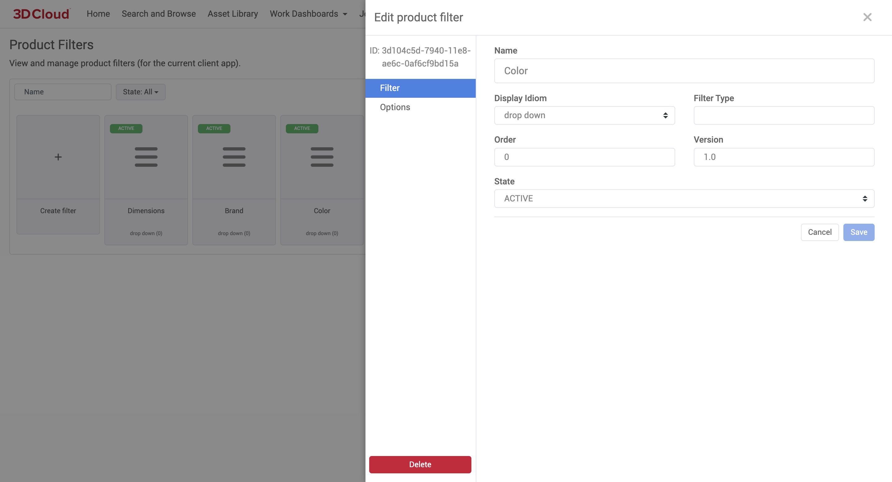
Product Filter Detail: Editing Existing Filter
Similar to product filters, options can be created via the “Add New Option” button on the product filter detail page, or the edit icon on the top-right of an existing Product Filter Option card.
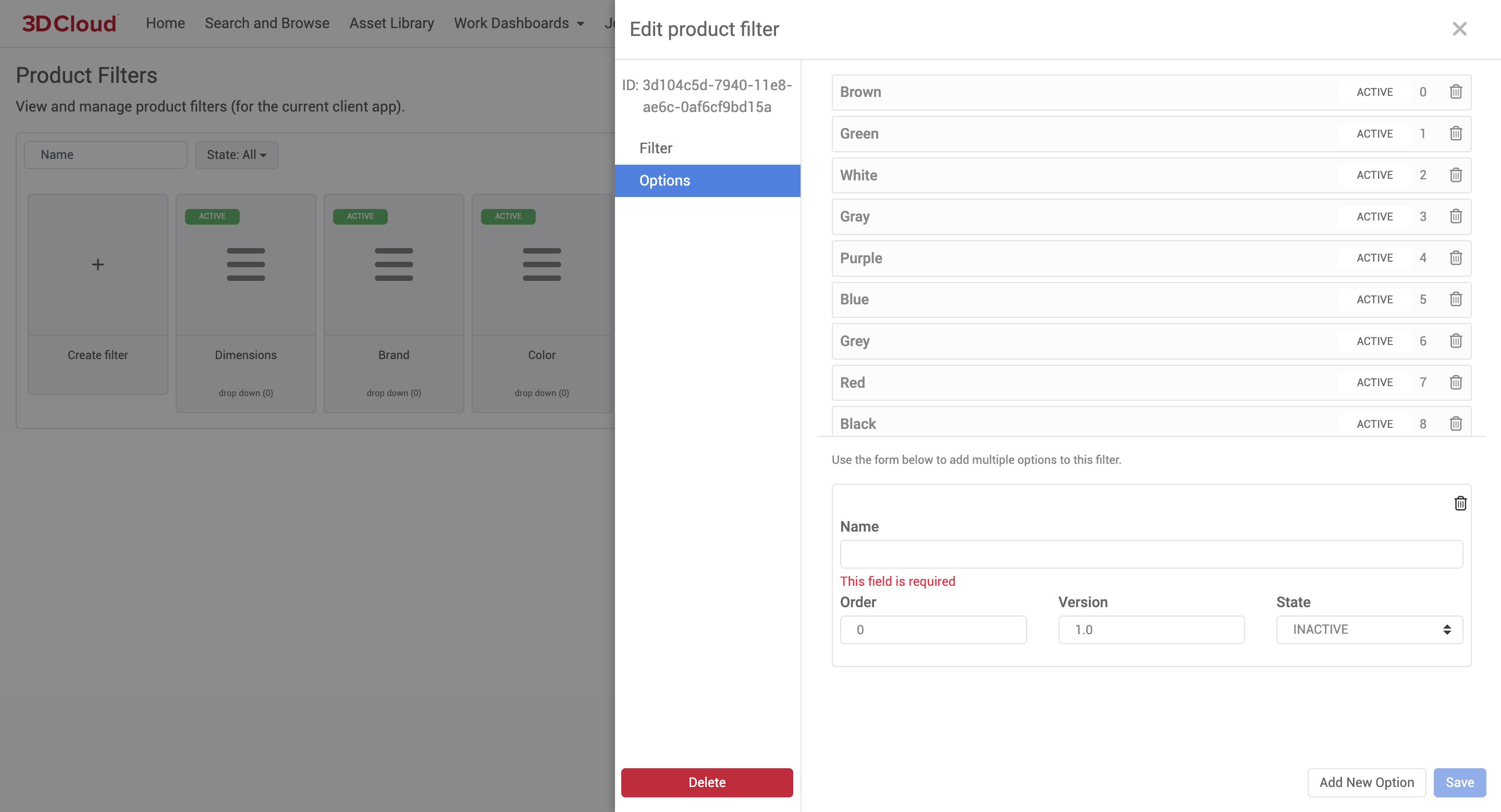
Product Filter Detail: Editing Existing Filter: Options
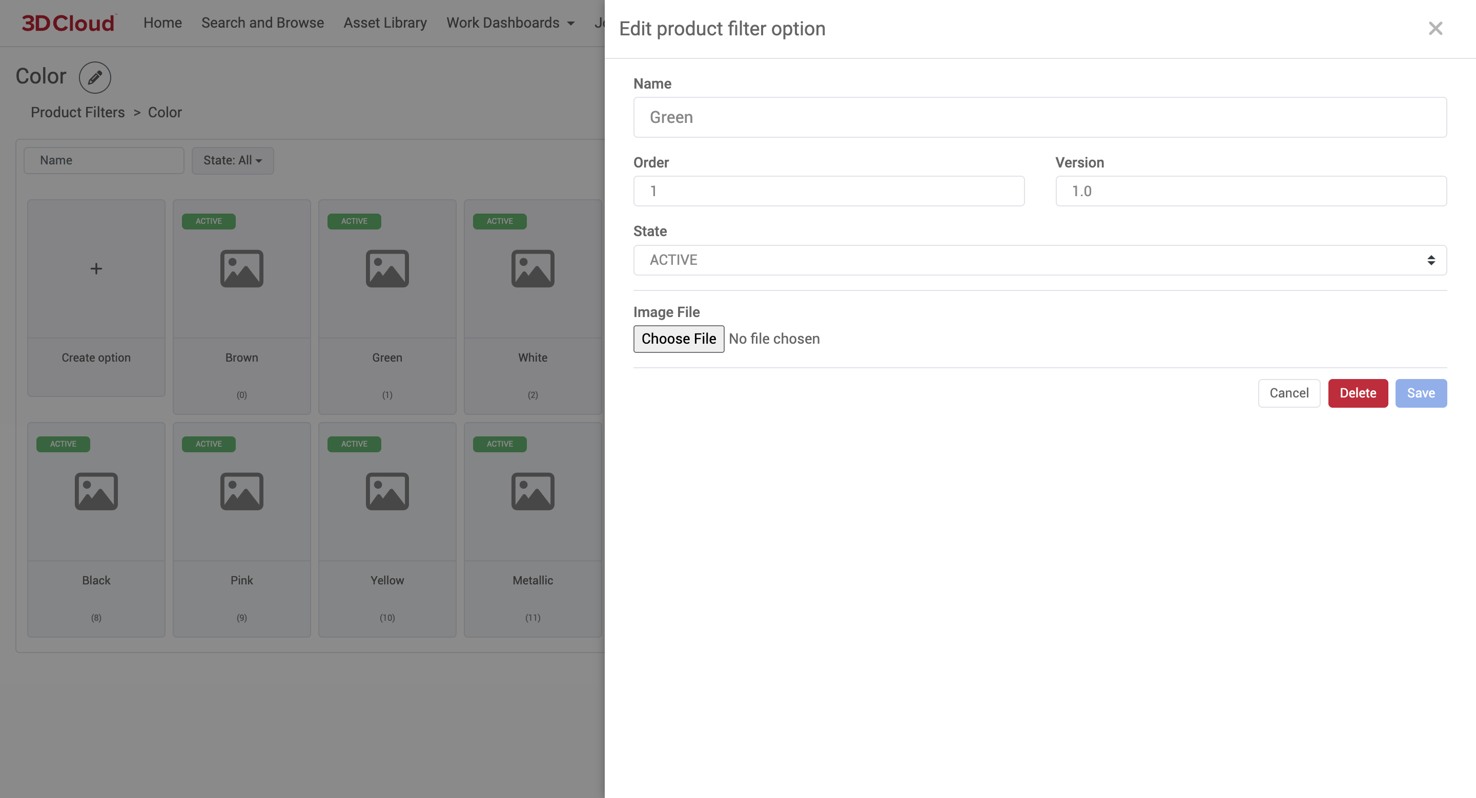
Product Filter Option Detail
Options cannot be deleted from this dialog. However, they can be removed from the Product Filter edit dialog.
WebAR
WebAR stands for "Web-based Augmented Reality." It is a technology that allows users to experience augmented reality (AR) directly through a web browser, without needing to download a separate app. With WebAR, users can view and interact with 3D models or AR content on their smartphones, tablets, or computers simply by visiting a website.
The 3D Cloud AMS WebAR toolset is a suite of utilities and SDKs designed to enable the creation, management, and deployment of Augmented Reality (AR) experiences directly in web browsers, supporting both iOS and Android devices. The Web AR Toolset is located in the 3D Cloud AMS under Utilities → WebAR.
To generate assets for WebAR, you will need to know which Client App ID you need to use to run the job.
Note: Typically, the Client App ID is from the WebGL or Room Planner app for any given client and typically NOT the WebAR app that you likely will also see an option for.
There is not a foolproof way to test this, but if assets have been generated for a client in the past you can use the Web AR PLP demo page to plug in the client and API key to confirm (see next section).
Web AR PLP Demo Page
A demo page has been set up that utilizes URL parameters to preview AR assets that already exist for a specific Client and Client App: Marxent | Web AR PLP Demo
.png)
WebAR PLP Demo Page
You will note that in the URL of this page, parameters are embedded. These can be customized as need be for the Client ID and apiKey (for the app). The example above is for a demo client and the apiKey is for a demo application.
&clientId=
&apiKey=
&lod=1024
&state=latest
When you are using the WebAR Toolset to generate WebAR assets, it is highly advised to go to this page before generating assets so you can confirm the correct App ID is used for the generation job and also validate the count increments after your generate assets job. In the image above you can see this client has 3502 webAR assets. You would expect this to increment after you run the job in the next section by the number of Product IDs (PIDs) you run.
Generating WebAR assets
While having the correct app for the client selected, go to Utilities → WebAR.

Click the “Generate Meshes” button and a panel will open to search for the existing Product IDs for which you want to generate WebAR assets.
Ensure you have “High” selected for resolution. There should be no reason ever to use anything other than High with the process how it is now. The last step is to click the “Convert Products” button at the bottom to convert products.
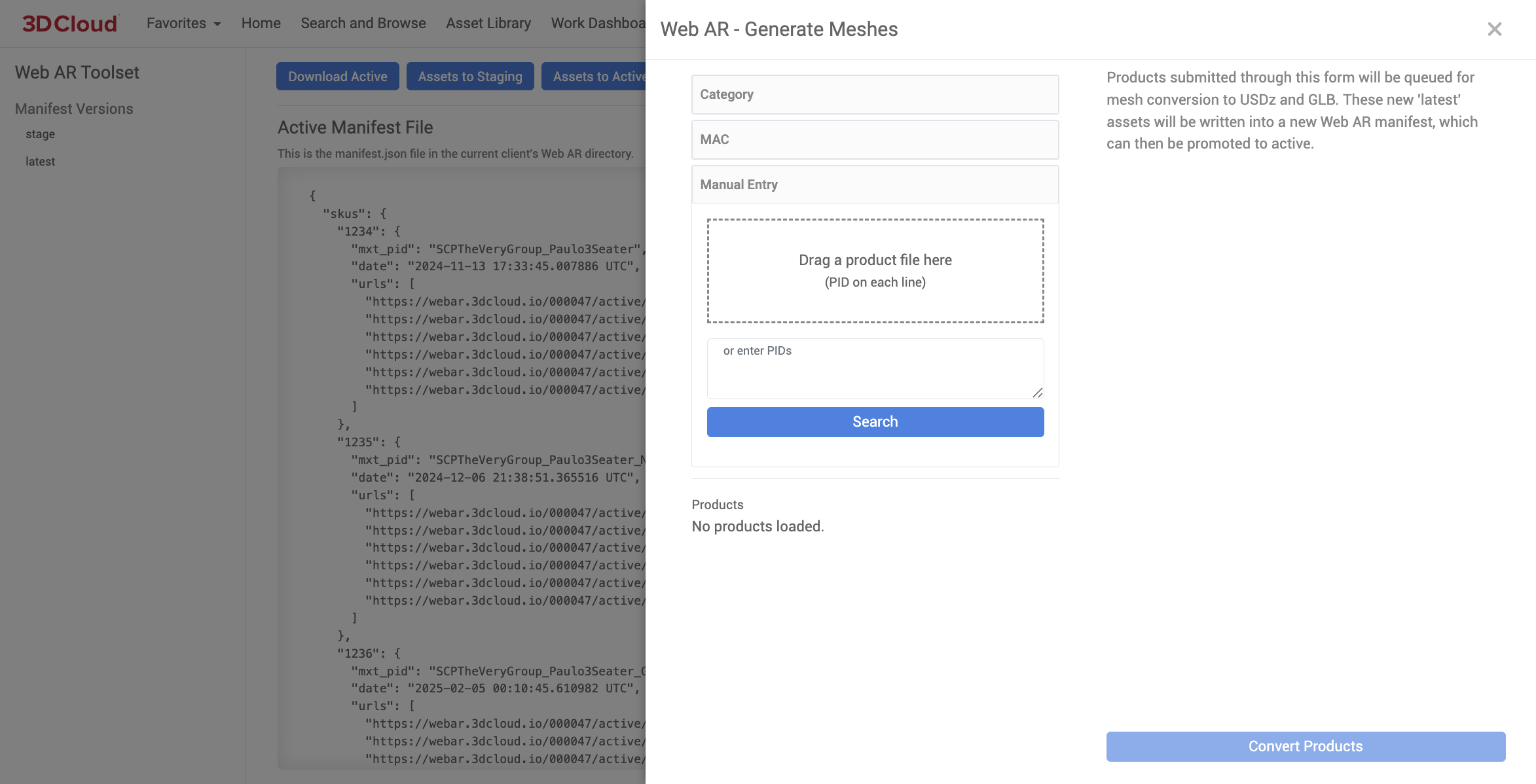
3D Product Configurator
The 3D Cloud Product Configurator section is where Product Configurators are built. Please refer to the 3D Product Configurator User Manual for more information on this application.
3D Cloud Product Configurators deliver a user-friendly, realistic, and fully customizable 3D or rendered configuration experience for home furnishings or Office procucts. The system is entirely no-code, allowing easy management of setup, updates, and pricing through our platform.
These configurators are designed for reuse across both product detail pages and the 3D Cloud Room Planner, maximizing content utility. The platform enables scalable visual specification of complex product catalogs for home furnishings, supporting both online and in-store retail environments. Customers benefit from increased clarity and confidence in their purchasing decisions.
For office products, Product Configurators allow the visual specification of complex, configurable product catalogs, scaling across e-commerce and physical retail environments. This ultimately enables greater clarity and purchasing confidence for customers.
.png)
Product Configurator for Home Furnishings
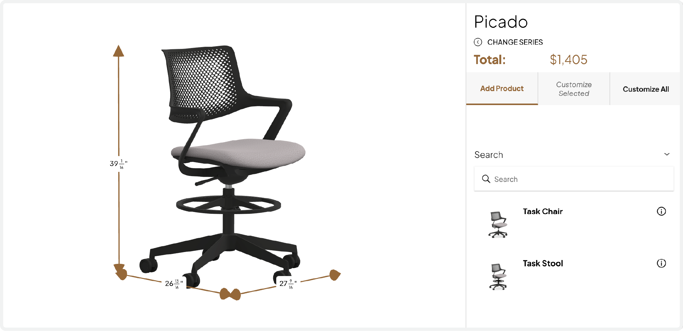
Product Configurator for Office